Spherical neutron generator

Inactive Publication Date: 2006-11-21
RGT UNIV OF CALIFORNIA
View PDF18 Cites 14 Cited by
  • Summary
  • Abstract
  • Description
  • Claims
  • Application Information

AI Technical Summary

Benefits of technology

[0009]This invention provides a high brightness neutron generator with a small target area and a high total ion current on the target, which thereby functions

Problems solved by technology

Neutron yield is limited by the ion source performance and beam size.
The production of neutrons is limited by the beam current and power deposition on the target.
In the conventional neutron tube, the extraction aperture and the target are limited to small areas, and so is the n

Method used


Image

  • Spherical neutron generator
  • Spherical neutron generator

Examples


Example

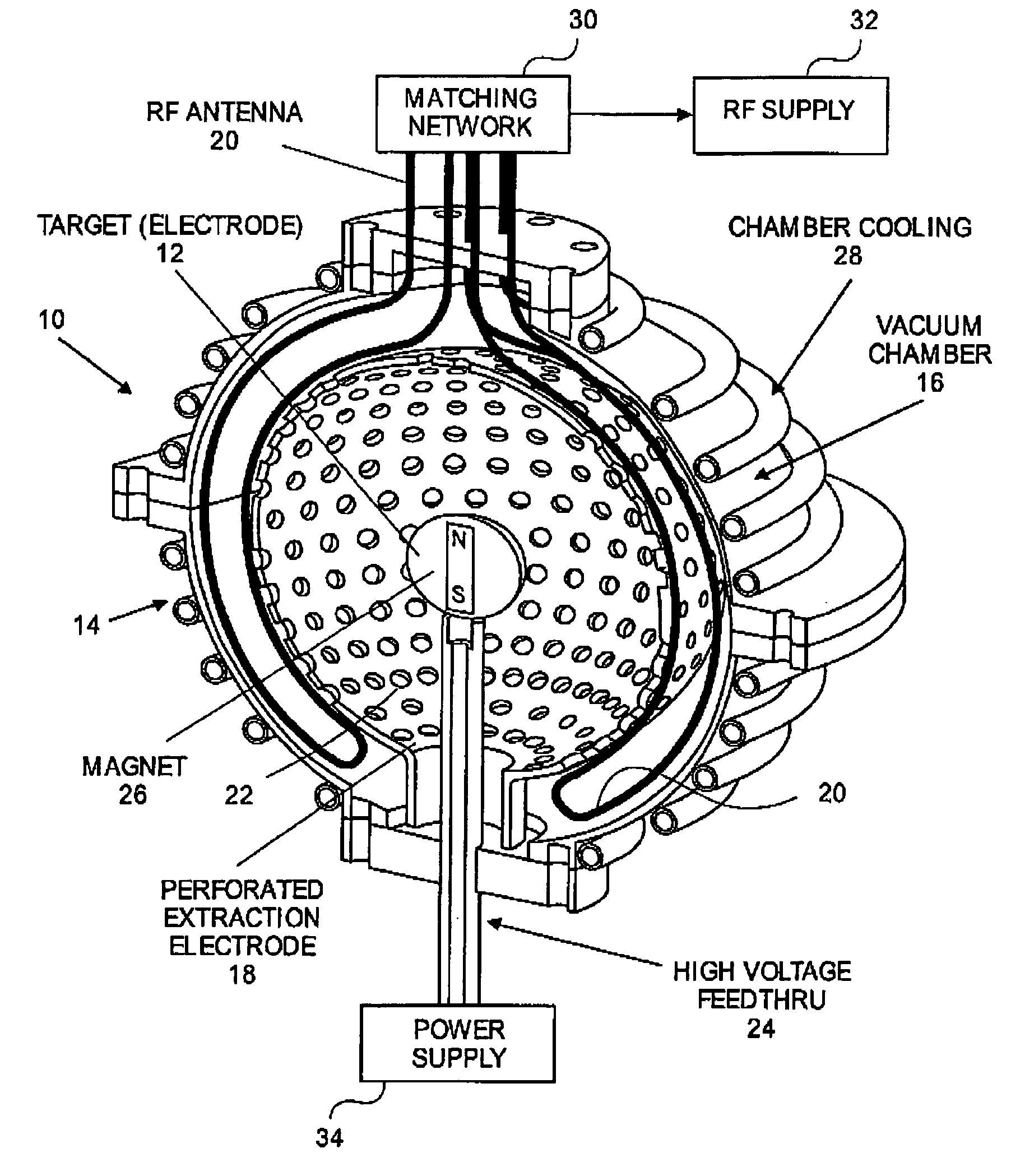
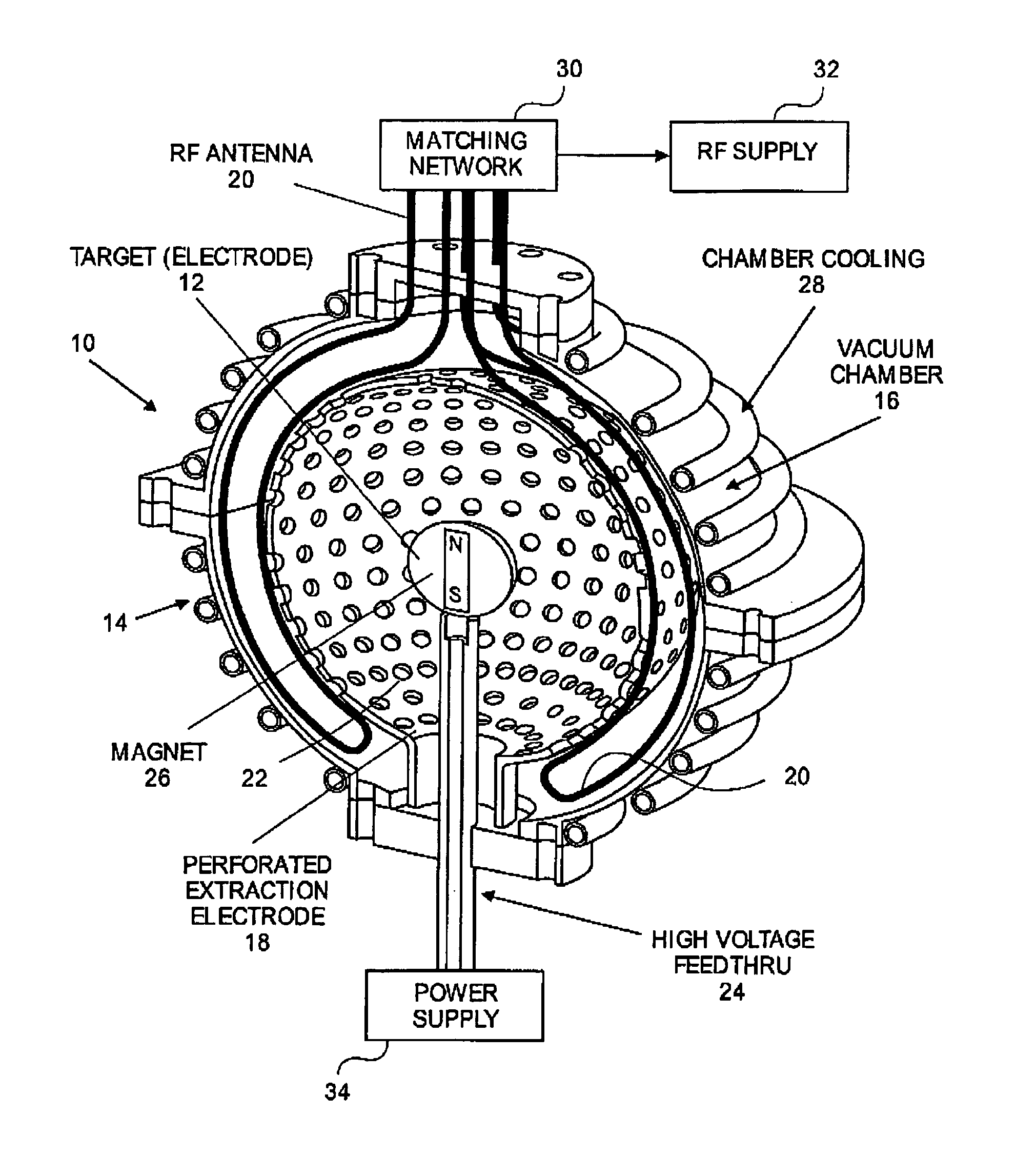
[0011]The FIGURE shows a spherical neutron generator 10 of the invention, which has a small spherical neutron generating target (electrode) 12 inside a spherical shell plasma ion source 14. Neutron generator 10 has a spherical target 12 at its center, surrounded by plasma ion source 14. Plasma ion source 14 is formed in the spherical shell defined between outer vacuum chamber 16 and inner perforated extraction electrode 18.

[0012]The principles of plasma ion sources are well known in the art. Preferably, ion source 14 is a magnetic cusp plasma ion source. Permanent magnets are arranged in a spaced apart relationship, on the outer surface of plasma ion generator 14, to from a magnetic cusp plasma ion source. The principles of magnetic cusp plasma ion sources are well known in the art. Conventional multicusp ion sources are illustrated by U.S. Pat. Nos. 4,793,961; 4,447,732; 5,198,677; 6,094,012, which are herein incorporated by reference.

[0013]Ion source 14 includes at least one RF an...


PUM


Abstract

A spherical neutron generator is formed with a small spherical target and a spherical shell RF-driven plasma ion source surrounding the target. A deuterium (or deuterium and tritium) ion plasma is produced by RF excitation in the plasma ion source using an RF antenna. The plasma generation region is a spherical shell between an outer chamber and an inner extraction electrode. A spherical neutron generating target is at the center of the chamber and is biased negatively with respect to the extraction electrode which contains many holes. Ions passing through the holes in the extraction electrode are focused onto the target which produces neutrons by D-D or D-T reactions.

Description

RELATED APPLICATIONS[0001]This application claims priority of Provisional Application Ser. No. 60 / 276,670 filed Mar. 16, 2001.GOVERNMENT RIGHTS[0002]The United States Government has rights in this invention pursuant to Contract No. DE-AC03-76SF00098 between the United States Department of Energy and the University of California.BACKGROUND OF THE INVENTION[0003]The invention relates to neutron tubes or sources, and more particularly to neutron tubes or sources based on plasma ion generators, including compact neutron tubes or sources which generate a relatively high neutron flux using the D-D reaction.[0004]Conventional neutron tubes employ a Penning ion source and a single gap extractor. The target is a deuterium or tritium chemical embedded in a molybdenum or tungsten substrate. Neutron yield is limited by the ion source performance and beam size. The production of neutrons is limited by the beam current and power deposition on the target. In the conventional neutron tube, the extr...

Claims


Application Information

Patent Timeline
IPC IPC(8): G21B1/00G21B3/00
CPCG21B3/00Y02E30/18Y02E30/10
Inventor LEUNG, KA-NGO
Owner RGT UNIV OF CALIFORNIA
Why Eureka
Try Eureka