Compact fiber optic geometry for a counter-chirp FMCW coherent laser radar

a fiber optic geometry and coherent laser technology, applied in the direction of acceleration measurement using interia force, using reradiation, instruments, etc., can solve the problems of inability to achieve the precision measurement of dimensions inside the chassis easily with known open beam systems, and the use of known systems is limited. , to achieve the effect of substantially reducing the uncertainty of composite absolute distance measuremen

Active Publication Date: 2006-11-21
NIKON METROLOGY
View PDF12 Cites 70 Cited by
  • Summary
  • Abstract
  • Description
  • Claims
  • Application Information

AI Technical Summary

Benefits of technology

[0020]There is also an interface at the beam exit end of the linear polarization-maintaining fiber, whereby a fraction of the transmitted light from each of the first coherent light beam and the second coherent light beam is reflected back toward the linear polarization splitter and thence transmitted respectively into the first fiber optic coupler and the second fiber optic coupler and whereby a complementary fraction of the transmitted light is transmitted to the target and returned to the interface from the target; a first optical detector optically connected to the first fiber optic coupler; whereby a first interference is established between the reflected fraction of the transmitted light from the first coherent light beam and the return of the first coherent light beam from the target and whereby the first optical detector detects a first beat frequency from the first interference; a second optical detector optically connected to the second fiber optic coupler; whereby a second interference is established between the reflected fraction of the transmitted light from the second coherent light beam and the return of the second coherent light beam from the target and whereby the second optical detector detects a second beat frequency from the second interference. Thereafter the beat frequency signal is sent to digital signal processing apparatus configured to produce a first beat frequency measurement and a second beat frequency measurement. In the most preferred embodiment a first calibrated reference arm standard is optically connected to the first fiber optic coupler and receives one of the two nominal 50 percent fractions of the first coherent light beam and further producing a first reference arm output; a second calibrated reference arm standard is optically connected to the second fiber optic coupler and receives one of the two nominal 50 percent fractions of the second coherent light beam and further producing a second reference arm output. Computer apparatus combines the first beat frequency measurement with the first reference arm output to produce a first absolute distance measurement, and further combines the second beat frequency measurement with the second reference arm output to produce a second absolute distance measurement. The computer apparatus further combines the first absolute distance measurement with the second absolute distance measurement to produce a composite absolute distance measurement, wherein uncertainty in the composite absolute distance measurement is substantially reduced.

Problems solved by technology

However, when the target location is such that limited free space is available for beam propagation, such known systems are of limited use.
Thus, known systems may be able to perform distance measurements, but the open beam optical sensor head prevents application in limited access areas and tight places.
For example, precision measurement of dimensions inside a chassis cannot easily by accomplished with known open beam systems.
While it is known to transfer light through optical fibers, precision is compromised due to the environmental effects on the fiber itself.
These environmental effects change the optical path length and the polarization of the light in the fiber, adversely affecting measurement precision.
However, Massie is an open beam system and thus incapable of accessing limited space targets.
The devices which have been demonstrated that are made in accord with the teachings of Chien et al., and Imai et al., and are slow, taking several seconds to integrate data to obtain a usable fringe image.
This overly lengthy time for analysis results in these devices being very sensitive to alignment and vibration.
When applied to the measurement of position of non-ideal surfaces such as anodized aluminum or the flanks of a tread, which are typically at a 30 degree angle of incidence to the interferometer beam, the signal-to-noise ratio becomes too small to make a reliable high resolution measurement.

Method used


Image

  • Compact fiber optic geometry for a counter-chirp FMCW coherent laser radar
  • Compact fiber optic geometry for a counter-chirp FMCW coherent laser radar
  • Compact fiber optic geometry for a counter-chirp FMCW coherent laser radar

Examples


example 1

Compact Counter-Chirp Geometry

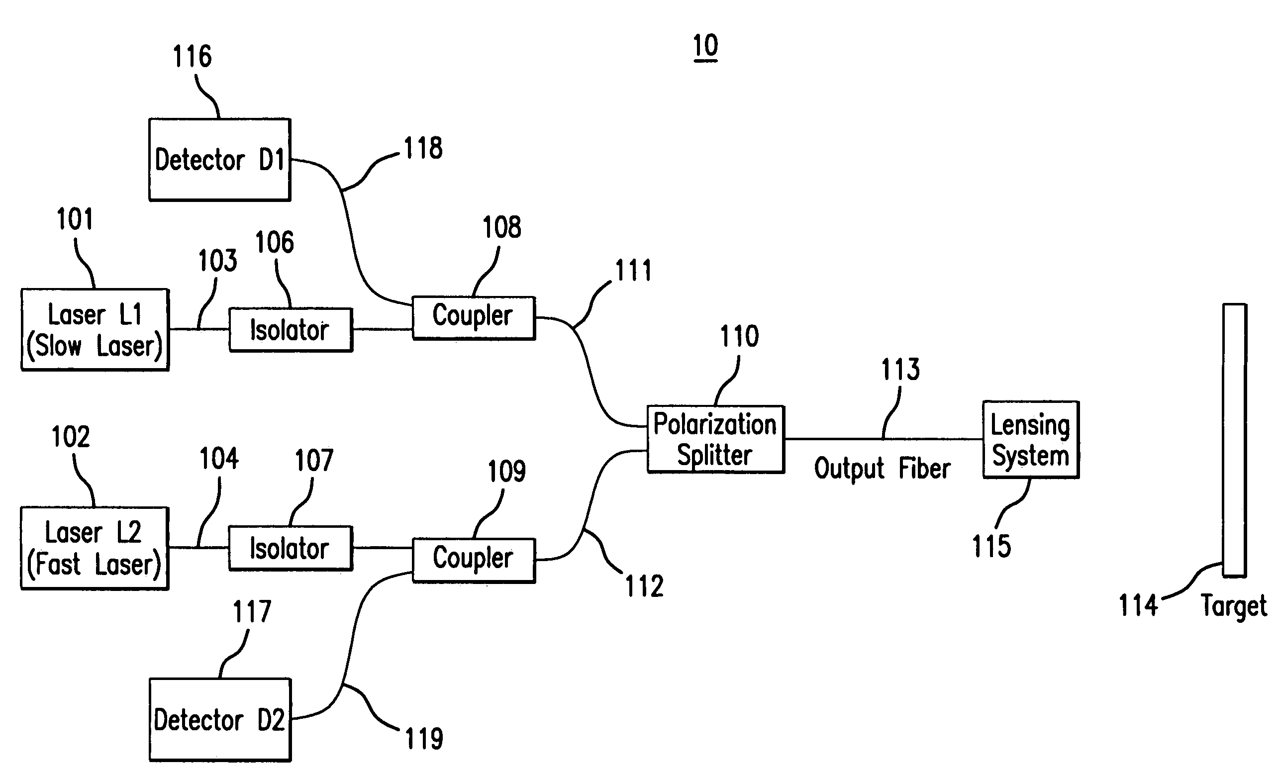
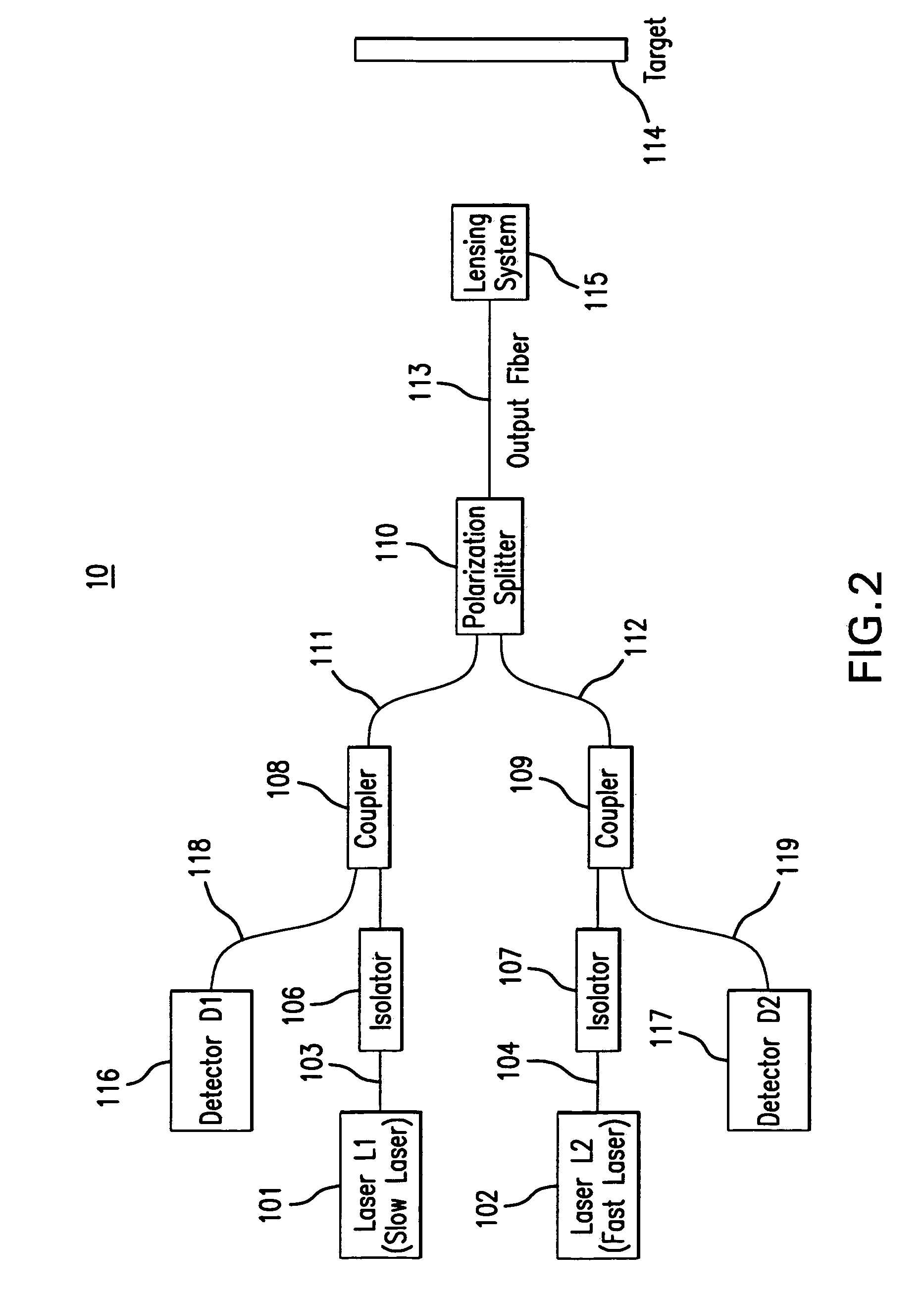
[0059]This disclosure presents a technique for using polarization maintaining (PM) optical fiber components in a polarization diplexing scheme to construct a version of the dual chirp coherent laser radar that is totally immune to environmental effects. FIG. 2 illustrates such a laser radar optical configuration, 10. The laser light is generated by two PM fiber pigtailed laser diodes (101, 102). In a related aspect, laser light may be generated by a fiber laser or solid-state laser source. The light from laser L1, 101, designated the slow laser, is aligned with the corresponding slow axis of the PM fiber, 103, The light from laser L2, 102, designated the fast laser, is aligned with the corresponding fast axis of the PM fiber, 104. The light from each laser passes through a corresponding fiber optic optional isolator (106, 107) to prevent back-reflected light from disrupting the lasers' tuning characteristics. In a related aspect, the isolator may be a f...

example 2

Compact Counter-Chirp Geometry, Including Reference Arm Standard

[0065]For precision measurements it is necessary to include a reference arm standard both for absolute ranging accuracy and to help linearize the lasers' chirp waveforms. This reference standard can take the form of a fiber optic interferometer in a Mach Zehnder configuration (e.g., see U.S. Pat. No. 4,552,457). Alternatively, a Michelson interferometer configuration may also be used (e.g., see U.S. Pat. No. 4,278,351). FIG. 5 illustrates the basic geometry, 12, with reference arm standards for each laser (120, 121). In this geometry, 12, the light from laser L1, 120, after passing through the isolator, 122, is received by a fiber coupler, 124. This coupler, 124, has a nominal 50 / 50 splitting ratio. Other splitting ratios are possible but are less desirable in terms of system performance. The light energy that is directed to the target is split into the signal and LO paths and detected as described in Example 1. The rem...

example 3

Compact Counter-Chirp Alternative Geometry, Including Reference Arm Standard

[0068]In an alternate fiber geometry, 15, the invention can be configured as illustrated in FIG. 7. In this configuration, 15, the light from lasers L1, 150, and L2, 151, after passing through their corresponding isolators (152, 153), are combined by a polarization splitter, 154. The light from the two lasers (150, 151) are received by a fiber optic coupler, 155, such that their orthogonal polarizations are preserved. The light energy that is directed to the target, 158, is split into the signal and the LO paths as described in Example 1 and is directed to the detectors D1, 165, and D2, 166, by means of the passing through the coupler, 155, again. A second polarization splitter, 159, directs the light in the LO and signal path from laser L1, 150, to detector D1, 165 and the light in the LO and signal path from laser L2, 151, to detector D2, 166. In a similar manner, light from the two lasers (150, 151) is in...


PUM


Abstract

This disclosure presents a non-contact precision optical device, including methods for measuring distances to an arbitrary target and various configuration geometries, for using polarization maintaining (PM) optical fiber components in a polarization diplexing scheme to construct a version of a dual chirp coherent laser radar that is immune to environmental effects.

Description

CROSS REFERENCE TO RELATED APPLICATIONS[0001]This application claims priority benefit of provisional patent application Ser. No. 60 / 653,490 filed Feb. 17, 2005, the contents of which are incorporated herein by reference.BACKGROUND OF THE INVENTION[0002]1. Field of the Invention[0003]The invention is a non-contact precision optical sensor for measuring distances to objects (targets) using coherent optical detection and two laser sources in a counter-chirp frequency modulated (FM) laser radar configuration[0004]2. Description of the Related Art[0005]Many optical systems exist which measure a distance to a target. Such systems utilize an open beam propagated through free space between the laser source and the target. However, when the target location is such that limited free space is available for beam propagation, such known systems are of limited use. Thus, known systems may be able to perform distance measurements, but the open beam optical sensor head prevents application in limit...

Claims


Application Information

Patent Timeline
Patent Type & Authority Patents(United States)
IPC IPC(8): G02B6/00G01B9/02G01P15/08G01S17/34G01S17/87
CPCG01S7/4818G01S7/497G01S7/499G01S17/325G01S17/87G01S17/34
Inventor SLOTWINSKI, ANTHONY
Owner NIKON METROLOGY
Why Eureka
Try Eureka