Method and apparatus for I/Q imbalance calibration of a transmitter system

a transmitter system and imbalance calibration technology, applied in the direction of pulse technique, transmitter monitoring, receiver monitoring, etc., can solve the problem of short model for analyzing the effects of signal impairment, most of the impairment can occur in either the transmitter or the receiver, and visible constellation distortion

Active Publication Date: 2006-11-21
MEDIATEK INC
View PDF3 Cites 54 Cited by
  • Summary
  • Abstract
  • Description
  • Claims
  • Application Information

AI Technical Summary

Problems solved by technology

While this is a good starting point for those unfamiliar with the technology, it falls short as a model for analyzing the effects of signal impairment.
In FDM systems, any overlap in the spectrums of adjacent signals will result in interference.
In OFDM systems, the carriers will interfere with each other only if there is a loss of orthogonality.
Most of these impairments can occur in either the transmitter or the receiver.
For example, gain mismatch might cause the I signal to be slightly smaller than the Q. In a single-carrier modulation system, this results in a visible distortion in the constellation—the square constellation of a 64-QAM signal would become rectangular.
Another way of saying this is that I / Q gain imbalance will result in each sub-carrier being interfered with by its frequency mirror-image sub-carrier.
This results in a spreading of the sub-carrier's constellation states in a noise-like fashion.
Quadrature skew produces error terms similar to those produced by gain imbalance.
The equalizer algorithm will be unable to differentiate the error from the actual channel response, and will interpret this as a channel with too much gain at these two sub-carrier frequencies.
Each QPSK sub-carrier also suffers from a bi-level gain error introduced by the equalizer.
This would produce eight groupings, except that the gain error is such that corners of the groupings overlap at the ideal corner state.
Delay mismatch is a distinct error.
This can be caused by different cable lengths (or traces), timing skew between D / A converters used to generate the I and Q signals, or group delay differences in filters in the I and Q signal paths.
What makes this error distinctive is that the error is greater for the outer carriers than it is for the inner carriers.
In other words, the error increases with distance from the center sub-carrier.
Phase noise results in each sub-carrier interfering with several other sub-carriers—especially those in close proximity.
Close-in phase noise that results in the constellation rotation for the data carriers also results in rotation of the pilot carriers.
Phase noise that is not considered to be close-in results in inter-carrier interference.
Instead of constellations with visible rotation, phase noise in an OFDM signal generally results in fuzzy constellation displays, similar to what would be expected if noise is added to the signal.
Unfortunately, there's another error mechanism that occurs at frequencies much lower than one-half the sample rate.
Phase noise causes the nulls of the sin(x) / x spectrum to fill in, creating interference between every sub-carrier and its neighbors.
A frequency error between the transmitter and the receiver will cause all of the sub-carriers to have a non-integral number of cycles in the FFT time interval, causing leakage.
The result is that frequency error causes every sub-carrier to interfere with its neighbors.
This presents the power amplifier designer with some difficult challenges.
Errors due to saturation will cause adjacent channel power problems, but may not have a large impact on data transmission—depending on the amount of dispersion in the transmission channel and the receiver's matched filter.
Because the OFDM time waveform is a summation of all sub-carriers, nonlinear distortion will create inter-carrier interference.
Of course, it will also result in increased adjacent channel power.

Method used


Image

  • Method and apparatus for I/Q imbalance calibration of a transmitter system
  • Method and apparatus for I/Q imbalance calibration of a transmitter system
  • Method and apparatus for I/Q imbalance calibration of a transmitter system

Examples


Embodiment Construction

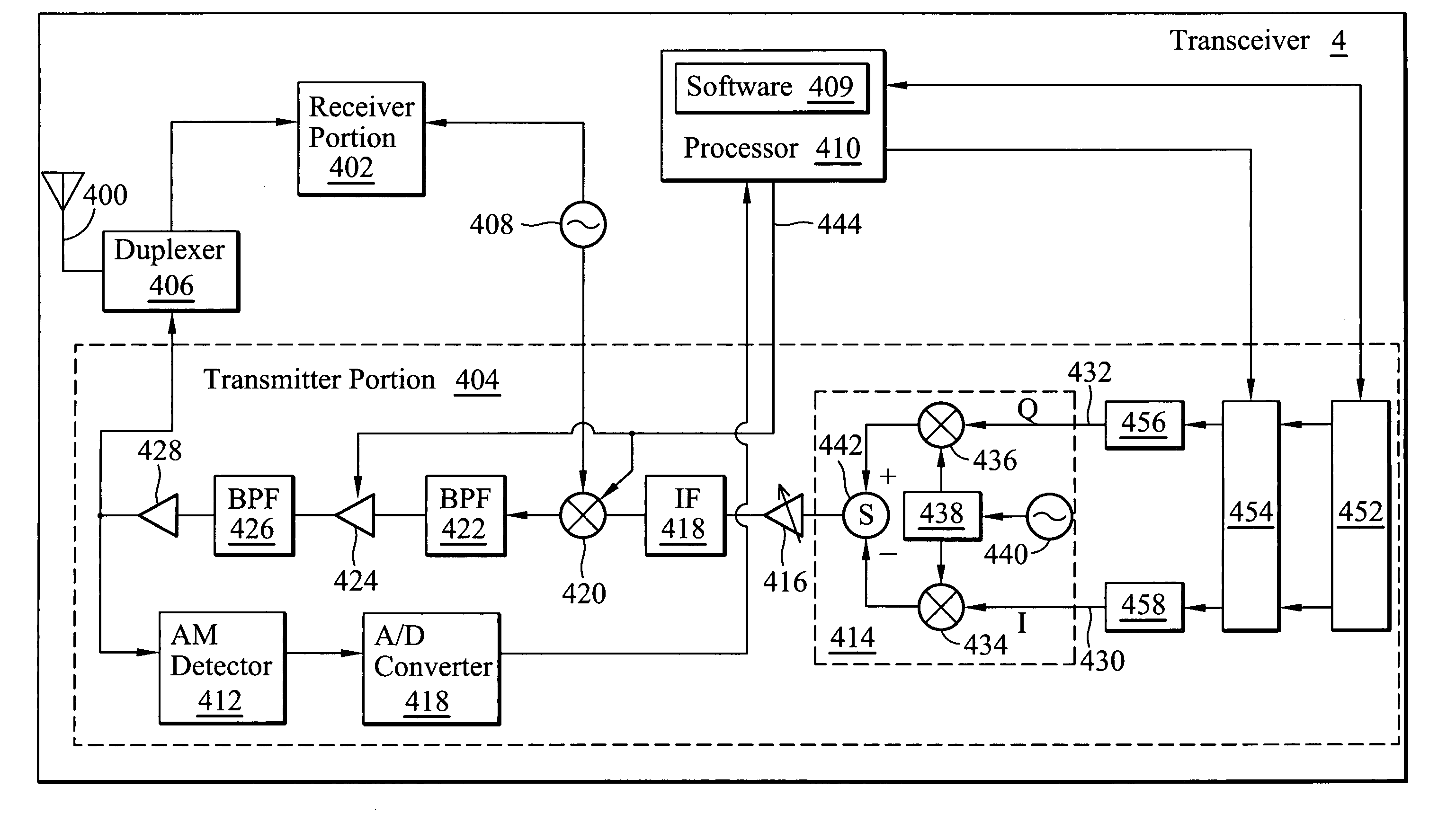
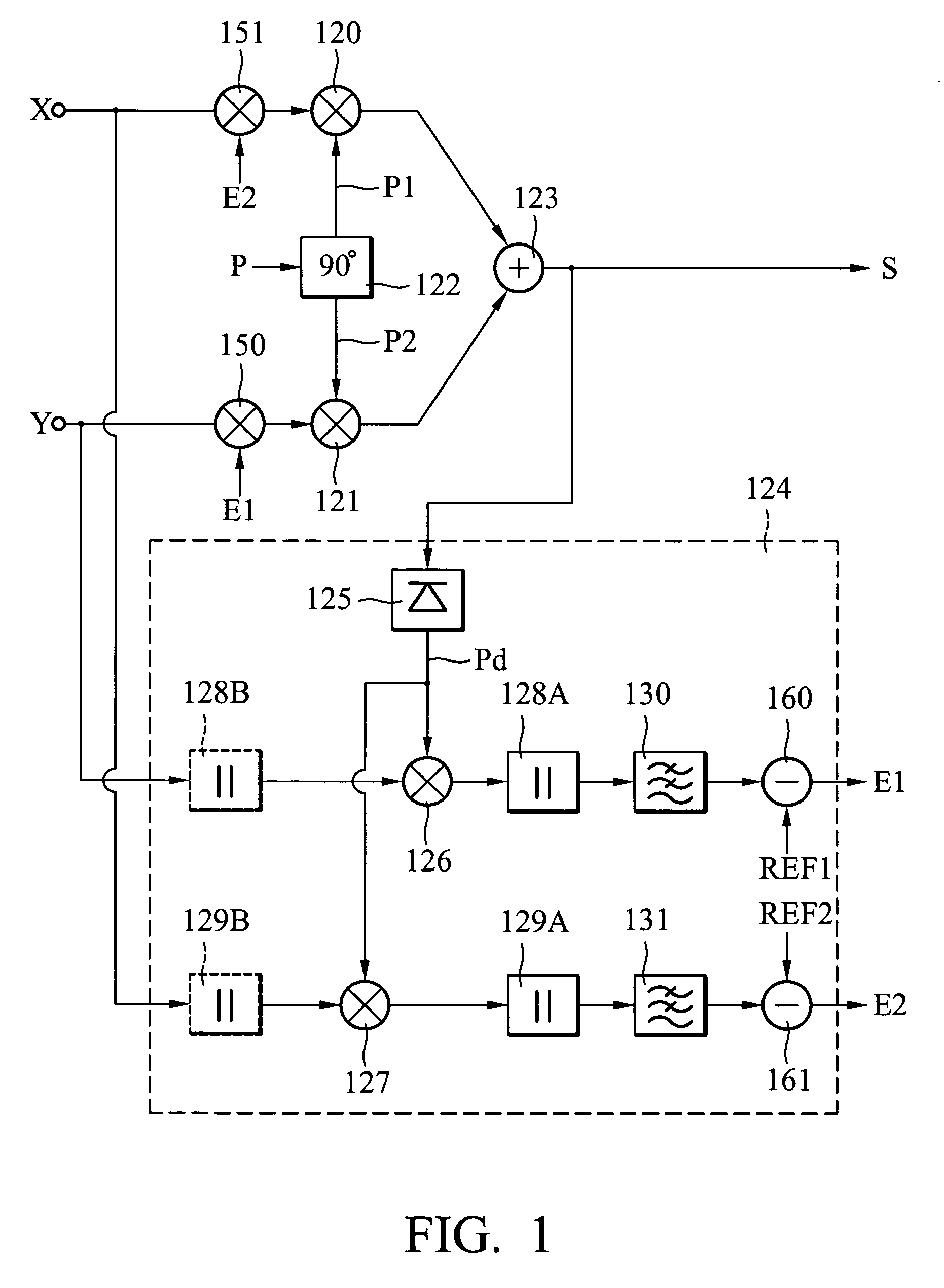
[0063]In the I / Q channel transmission architecture, there are two major sources of I / Q imbalance. One is the I / Q modulation and the other is the I / Q transmission band filtering. The mismatch resulting from the I / Q modulation is modeled as a constant over the useful signal bandwidth, which is called systematic I / Q imbalance while the I / Q transmission band filtering causes frequency-dependent I / Q imbalance. The present invention concentrates on the systematic I / Q imbalance. The mathematical theories of the invention will be described in the following.

[0064]The baseband signals for the I and Q channels before the I / Q modulation are represented as xI(t) and xQ(t) respectively. Assuming that an amplitude mismatch α, a phase mismatch θ, and zero local leakage results from the I / Q modulation, the equivalent baseband signals yI(t) and yQ(t) for the I and Q channels after the I / Q modulation are, without loss of generality, given by the equations:

yI(t)=xI(t)·(1+α)·cos(θ / 2)+xQ(t)·(1−α)·sin(θ / 2...


PUM


Abstract

A method for I / Q imbalance calibration of an OFDM system comprising the steps of initializing parameters Ap, Bp and γp, estimating a loop delay factor L, generating a discrete-time test signal x[n], deriving a signal xcom[n] by compensating the test signal x[n] according to a function with parameters Ap, Bp and γp, converting the signal xcom[n] to an analog signal x(t), applying I / Q modulation to the signal x(t) and outputting a modulated signal xmod(t), obtaining a characteristic signal xc(t) of the modulated signal, obtaining a signal xs[n] by sampling the characteristic signal xc(t) and obtaining statistics U1 and U2 of the signal xs[n], and updating the parameters Ap, Bp and γp respectively by functions of L, U1, U2, and the current values of Ap, Bp and γp.

Description

BACKGROUND OF THE INVENTION[0001]1. Field of the Invention[0002]The present invention relates to compensation of physical layer impairments on transmitter systems and particularly to a method and apparatus for I / Q imbalance calibration in transmitter systems.[0003]2. Description of the Prior Art[0004]OFDM is a multi-channel modulation system employing Frequency Division Multiplexing (FDM) of orthogonal sub-carriers, each modulating a low bit-rate digital stream. The simplest way to describe an orthogonal frequency-division multiplexing (OFDM) signal is as a set of closely spaced frequency-division multiplexed carriers. While this is a good starting point for those unfamiliar with the technology, it falls short as a model for analyzing the effects of signal impairment.[0005]The reason it falls short is that the carriers are more than closely spaced; they are heavily overlapped. In a perfect OFDM signal, the orthogonality property prevents interference between overlapping carriers. Th...

Claims


Application Information

Patent Timeline
Patent Type & Authority Patents(United States)
IPC IPC(8): H04B11/00H03C3/40H04B17/00
CPCH03C3/406H04B17/21H04B17/11
Inventor CHIU, MAO-CHING
Owner MEDIATEK INC
Why Eureka
Try Eureka