Low core loss magnetic alloy with high saturation magnetic flux density and magnetic parts made of same

a magnetic alloy and low core loss technology, applied in the direction of magnetic materials, magnetic bodies, inductance/transformer/magnet manufacture, etc., can solve the problems of low saturation magnetic flux density of ferrite materials, poor temperature characteristics, large core losses, etc., to achieve low core loss, high saturation magnetic flux density, the effect of easy production

Active Publication Date: 2006-11-28
HITACHI METALS LTD
View PDF13 Cites 11 Cited by
  • Summary
  • Abstract
  • Description
  • Claims
  • Application Information

AI Technical Summary

Benefits of technology

[0008]Accordingly, it is an object of the present invention to provide a magnetic alloy having a high saturation magnetic flux density and a low core loss, and capable of being further easily produced, and magnetic parts made of the alloy.

Problems solved by technology

However, ferrite materials are generally low in a saturation magnetic flux density, poor in a temperature characteristic, and are not suitable for applications of high power in which a large operation magnetic flux density is needed, from a reason that the ferrites are liable to saturate magnetically.
With regard to the silicon steels, they are large in the core losses with respect to the application at a high frequency, although they are not expensive, and have high in the saturation magnetic flux densities.
In the case of Fe-base amorphous alloys, problems are posed that they have large magnetostriction and their characteristics are deteriorated resulting from stresses they undergo, and that they generate large noises in the applications such as a case where currents of an audible frequency band are superposed.
On the other hand, in Co-base amorphous alloys, there are problems that its practical material has a low saturation magnetic flux density so as to have not more than 1 T (tesla), and is thermally unstable.
Therefore, when the Co-base amorphous alloys are used for the application of high power, there cause problems that size of magnetic parts made of the alloy become large and that the core losses of them are increased because of aged deterioration.
However, it is difficult to realize the high saturation magnetic flux density and the low core loss in these alloys.
However, in the Fe—Cu—Nb—Si—B alloy corresponding to a representative nano-crystalline soft magnetic alloy, it is difficult to realize the low core loss in a condition where the saturation magnetic flux density exceeds 1.65 T. Furthermore, even when Co is added, a remarkable increase of the saturation magnetic flux density cannot be confirmed.
On the other hand, in an Fe—Zr—B alloy or an Fe—Nb—B alloy, materials increasing the saturation magnetic flux densities to not less than 1.65 T become hard to form, and it is difficult to produce the materials in large amount.
Furthermore, the materials have drawbacks that they are poor in the temperature characteristics because their core losses increase rapidly in association with the elevation in temperature.
Although such drawbacks that the materials are poor in the temperature characteristics are dissolved and features of high saturation magnetic flux densities are included in them through the addition of Co, these alloys which are heat treated in a non-magnetic field have a problem that their core losses are remarkably large compared with Fe-base materials having no addition of Co.
Therefore, these alloys are difficult to be used for the various magnetic parts described above.
Furthermore, these alloys have a problem in terms of a short life of nozzle, because reactivity of the alloys with the nozzle is enhanced in the case of producing them in the large amount.

Method used


Image

  • Low core loss magnetic alloy with high saturation magnetic flux density and magnetic parts made of same
  • Low core loss magnetic alloy with high saturation magnetic flux density and magnetic parts made of same
  • Low core loss magnetic alloy with high saturation magnetic flux density and magnetic parts made of same

Examples


example 1

[0032]A molten alloy having a composition represented by the general formula:

(Fel-aCoa)bal.Cu0.7Nb6.8Si0.4B9.2(atomic %)

was rapidly quenched by a single roll method to produce an amorphous alloy ribbon of 5 mm in width and 18 μm in thickness. Next, this amorphous alloy ribbon was wound into dimensions of 19 mm in outer diameter and 15 mm in inner diameter to produce a toroidal core.

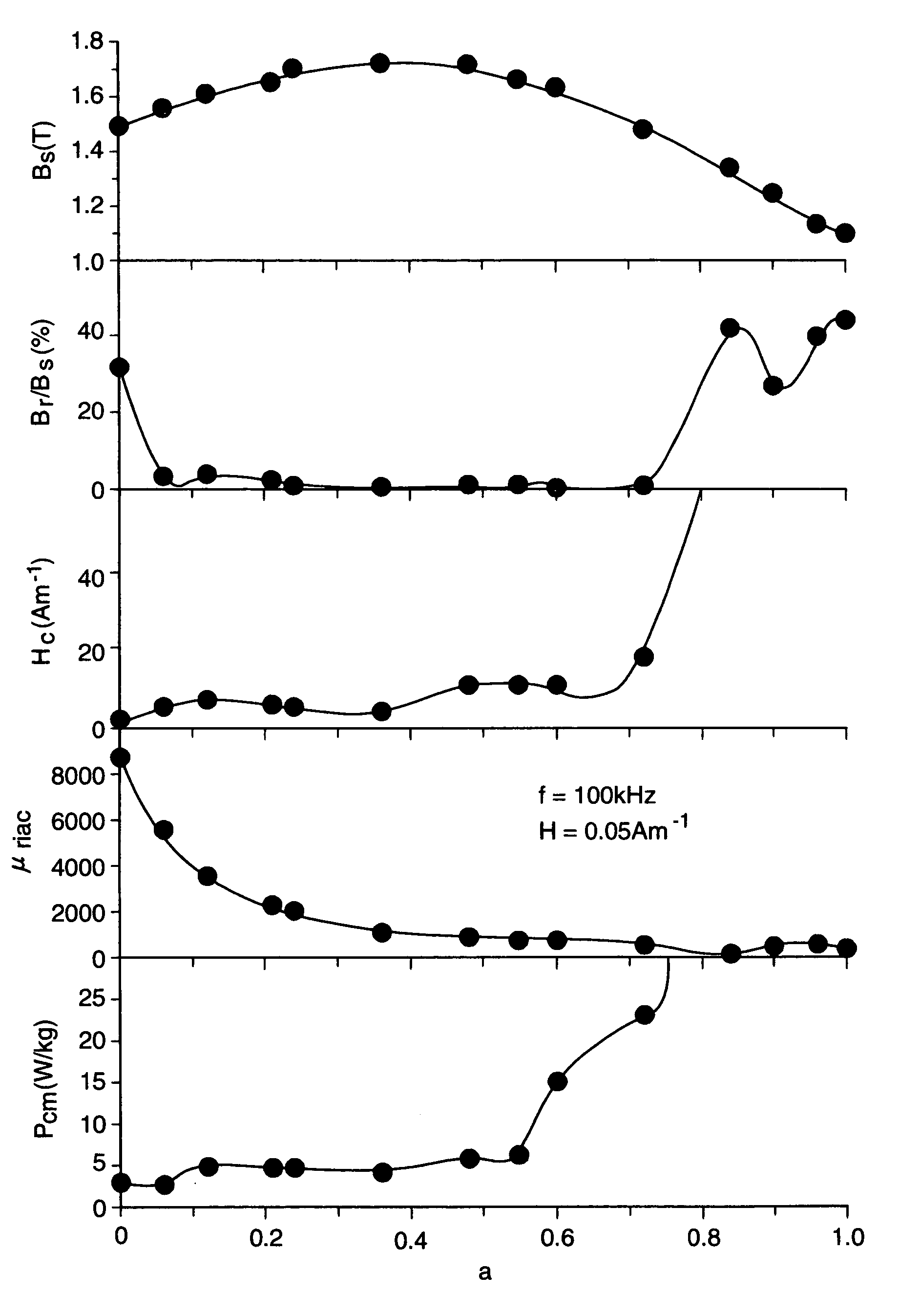
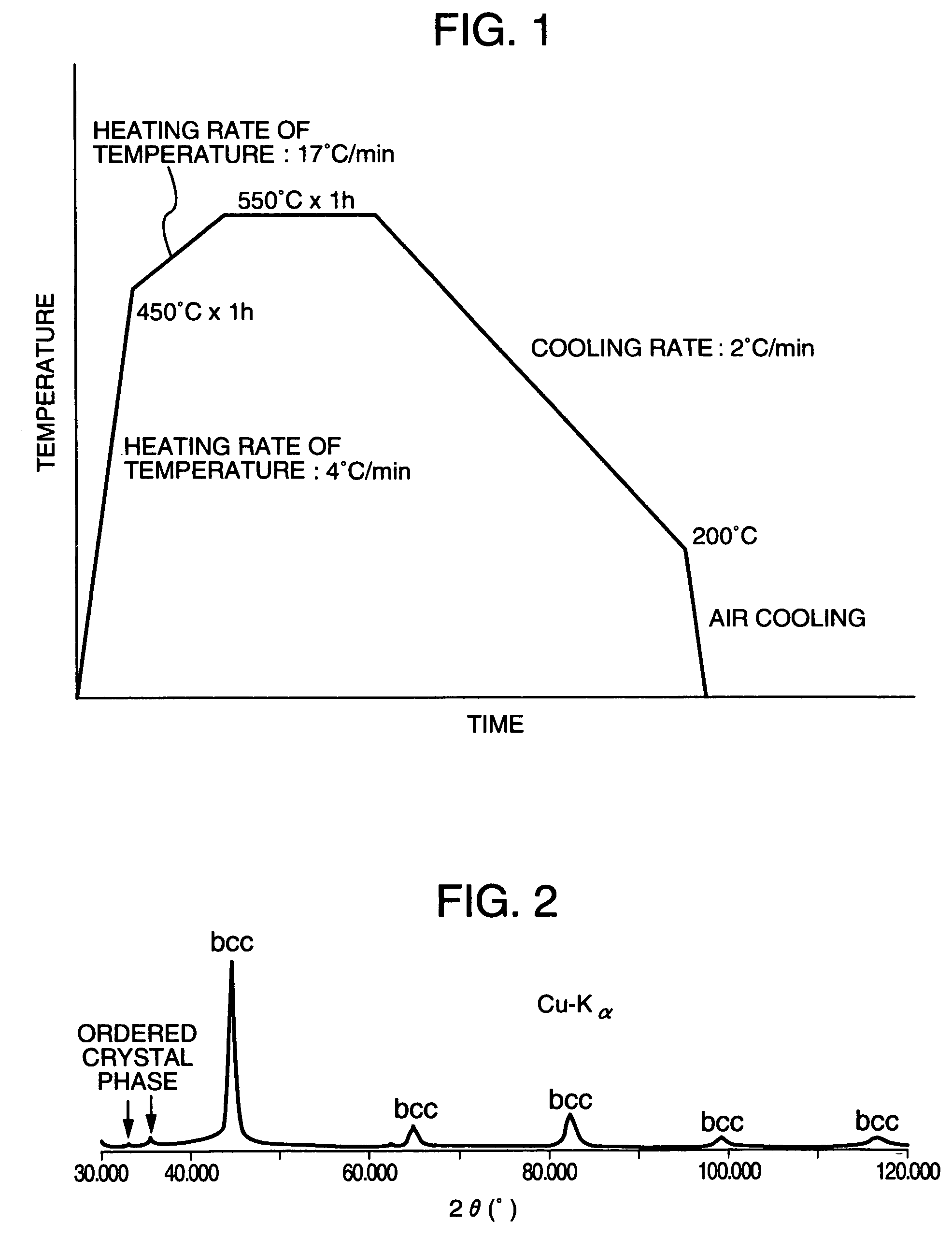
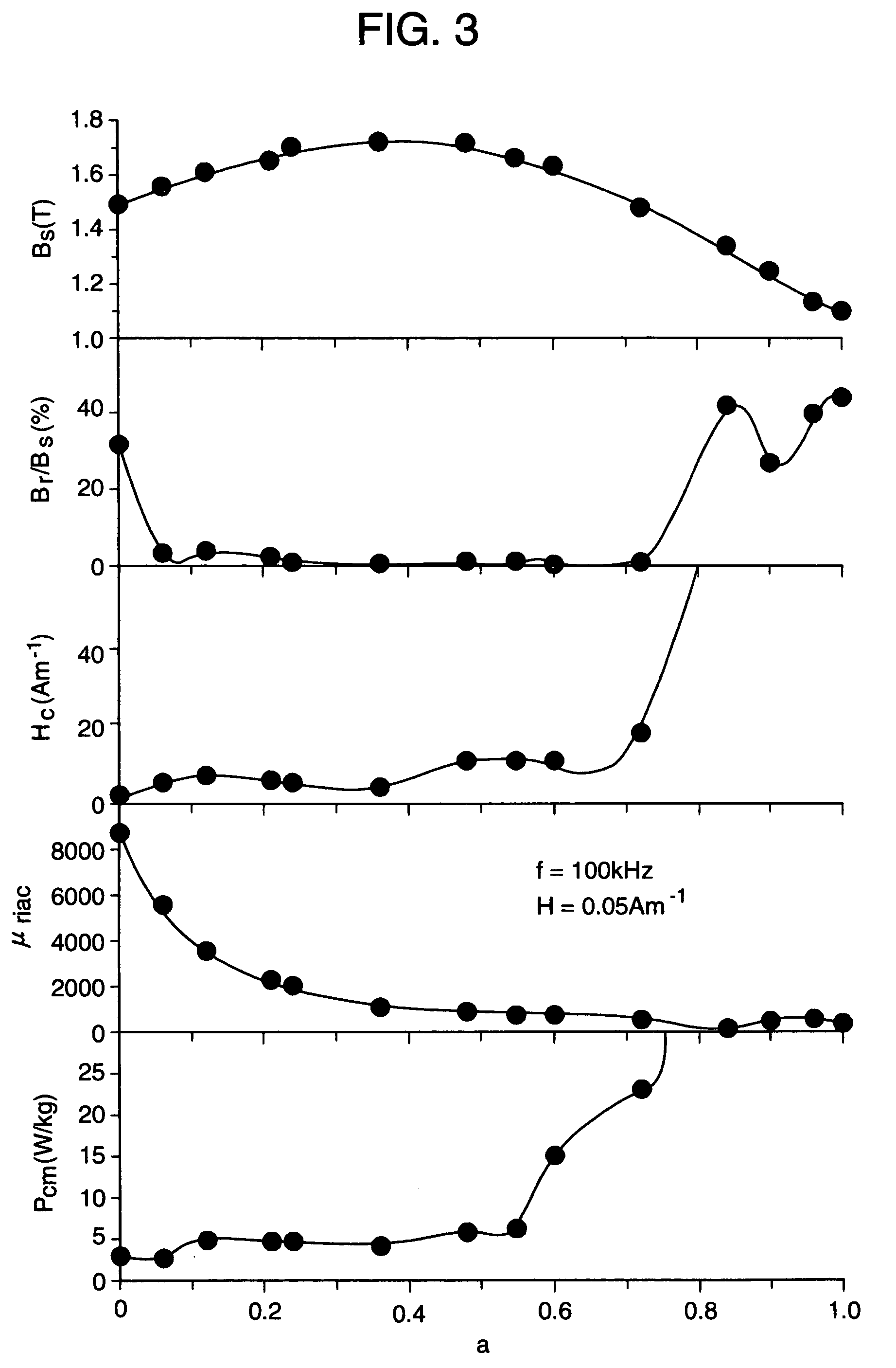
[0033]Thus produced magnetic core is inserted into a heat treatment furnace in a nitrogen gas atmosphere, and is subjected to a heat treatment with a pattern of the heat treatment shown in FIG. 1. During the heat treatment, a magnetic field of 280 kAm−1 is applied in a direction perpendicular (width direction of alloy ribbon) to a magnetic path of an alloy core, that is, in a height direction of the core. An alloy after the heat treatment is crystallized, and as a result of an observation by an electron microscope it is found that most of the alloy structures were occupied by fine crystal grains of body c...

example 2

[0035]A molten alloy having compositions shown in table 1 was rapidly quenched by a single roll method in an Ar gas atmosphere to produce an amorphous alloy ribbon of 5 mm in width and 18 μm in thickness. This amorphous alloy ribbon was wound into dimensions of 19 mm in outer diameter and 15 mm in inner diameter to produce a toroidal core. This alloy core is subjected to a heat treatment with a pattern of the heat treatment similar to that in the example 1 to make measurement with respect to its magnetism. Within an alloy structure after the heat treatment, ultrafine crystal grains with grain size of not larger than 50 nm are formed in a parent amorphous phase. Main crystal phases are body centered cubic (bcc) phases containing mainly Fe and Co and when containing Cu or Au, although X-ray analyses of them is not clear and they are not listed in a table, it was confirmed as a result of electron beam diffraction by the use of an electron microscope that face centered cubic (fcc) phase...

example 3

[0037]A molten alloy 150 g having a composition shown in a table 2 was rapidly quenched by a single roll method in an Ar gas atmosphere to produce an amorphous alloy ribbon of 5 mm in width and 18 μm in thickness. As nozzles, quartz nozzles are used. The amorphous alloy ribbons are repeatedly produced by using the used nozzle, and the number of usable times of the nozzle until production of the ribbons having specified widths becomes difficult are studied. Obtained results are shown in the table 2. Furthermore, this amorphous alloy ribbon is wound into dimensions of 19 mm in outer diameter and 15 mm in inner diameter to produce a toroidal core. This alloy core is subjected to a heat treatment with a pattern of the heat treatment similar to that in the example 1 to make measurement with respect to its magnetism. Within an alloy structure after the heat treatment, ultrafine crystal grains with grain size of not larger than 50 nm are formed. Main crystal phases are body centered cubic ...


PUM

PropertyMeasurementUnit
grain sizeaaaaaaaaaa
saturation magnetic flux density Bsaaaaaaaaaa
saturation magnetic flux densityaaaaaaaaaa

Abstract

A low core loss magnetic alloy with a high saturation magnetic flux density, which has a composition represented by the general formula:(Fel-aCoa)100-y-cM′yX′c(atomic %)where M′ represents at least one element selected from V, Ti, Zr, Nb, Mo, Hf, Ta, and W, X′ represents Si and B, an Si content (atomic %) is smaller than a B content (atomic %), the B content is from 4 to 12 atomic %, and the Si content is from 0.01 to 5 atomic %, a, y, and c satisfy respectively 0.2<a<0.6, 6.5≦y≦15, 2≦c≦15, and 7≦(y+c)≦20, at least a part of an alloy structure being occupied by crystal grains having grain size of not larger than 50 nm, a saturation magnetic flux density Bs being not less than 1.65 T, and a core loss Pcm per unit volume in conditions at 80° C., f=20 kHz, and Bm=0.2 T being not more than 15 W / kg.

Description

FIELD OF THE INVENTION[0001]The present invention relates to a low core loss magnetic alloy with a high saturation magnetic flux density showing particularly the low core losses and high performance magnetic parts made of the alloy, which are used for reactors for a large current, choke coils for an active filter, smoothing choke coils, various transformers, parts for a countermeasure of noise such as common mode choke coils and magnetic shields, power supplies for laser, pulse power magnetic parts for accelerators, motors, generators, and others.BACKGROUND OF THE INVENTION[0002]Silicon steels, ferrites, amorphous alloys, and Fe-base nano-crystalline alloy materials, or others are known as soft magnetic materials used for reactors for the large current, the choke coils for the active filter, the smoothing choke coils, the various transformers, the parts of the countermeasure of noise such as the magnetic shield material, power supplies for laser, the pulse power magnetic parts for t...

Claims


Application Information

Patent Timeline
Patent Type & Authority Patents(United States)
IPC IPC(8): H01F1/147C22C38/00H01F1/14H01F1/153H01F41/02
CPCH01F1/15316H01F1/15333H01F41/0226
Inventor YOSHIZAWA, YOSHIHITO
Owner HITACHI METALS LTD
Why Eureka
Try Eureka