Manufacturing method of phosphor or scintillator sheets and panels suitable for use in a scanning apparatus

a technology of phosphor or scintillator and scanning apparatus, which is applied in the direction of conversion screens, instruments, alkali metal bromides, etc., can solve the problems of difficult to obtain a layer with a constant thickness, production methods cannot be used to produce high-quality screens, and large amount of expensive residues

Inactive Publication Date: 2006-11-28
T2PHARMA GMBH
View PDF12 Cites 5 Cited by
  • Summary
  • Abstract
  • Description
  • Claims
  • Application Information

AI Technical Summary

Benefits of technology

[0019]The above-mentioned advantageous effects have been advantageously realized by a particular manufacturing method having the specific features set out in claim 1. Specific features for preferred embodiments of the invention are set out in the dependent claims and in the drawings.

Problems solved by technology

However, this production method can not be used to produce high quality screens with every arbitrary phosphor available.
Moreover, when square or rectangular panels are desired, quite a lot of expensive residue is created while not being deposited onto the plate, rotating with a circular symmetry above the vapor source.
In addition, when depositing material from a fixed source onto such a rotating substrate, it is difficult to obtain a layer with a constant thickness.
This creates a centro-symmetric thickness profile, which means that the thickness of the deposited layer is constant along neither of the sides of a rectangular substrate, unless special precautions are taken, e.g. use of a mask which will however lead to material losses.
In such a batch process a coating failure will generally lead to the complete loss of a panel.
Moreover there will always be a high loss of raw materials in such batch processes.
Lack of deformability of the substrate also limits the format of the coating of a phosphor or scintilator layer on a substrate to the largest cross section of the vacuum deposition chamber.

Method used


Image

  • Manufacturing method of phosphor or scintillator sheets and panels suitable for use in a scanning apparatus
  • Manufacturing method of phosphor or scintillator sheets and panels suitable for use in a scanning apparatus
  • Manufacturing method of phosphor or scintillator sheets and panels suitable for use in a scanning apparatus

Examples


##ventive example 1

Inventive Example 1

[0088]A CsBr:Eu photostimulable phosphor screen having a flexible anodized aluminum was prepared in a vacuum chamber by means of a thermal vapor deposition process, starting from a mixture of CsBr and EuOBr as raw materials. Said deposition process onto said flexible anodized aluminum support was performed in such a way that said support was moving so that the momentary magnitude of the velocity was constant over its whole area.

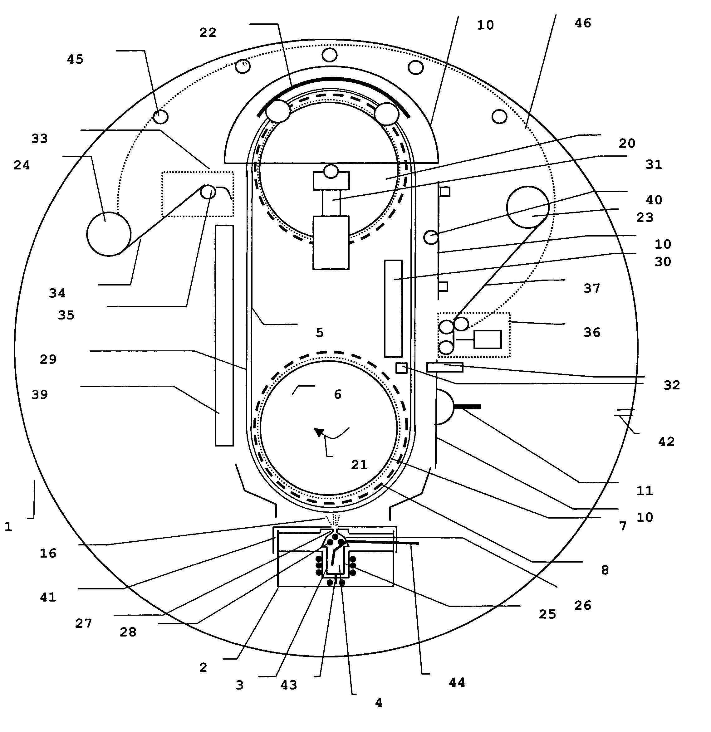
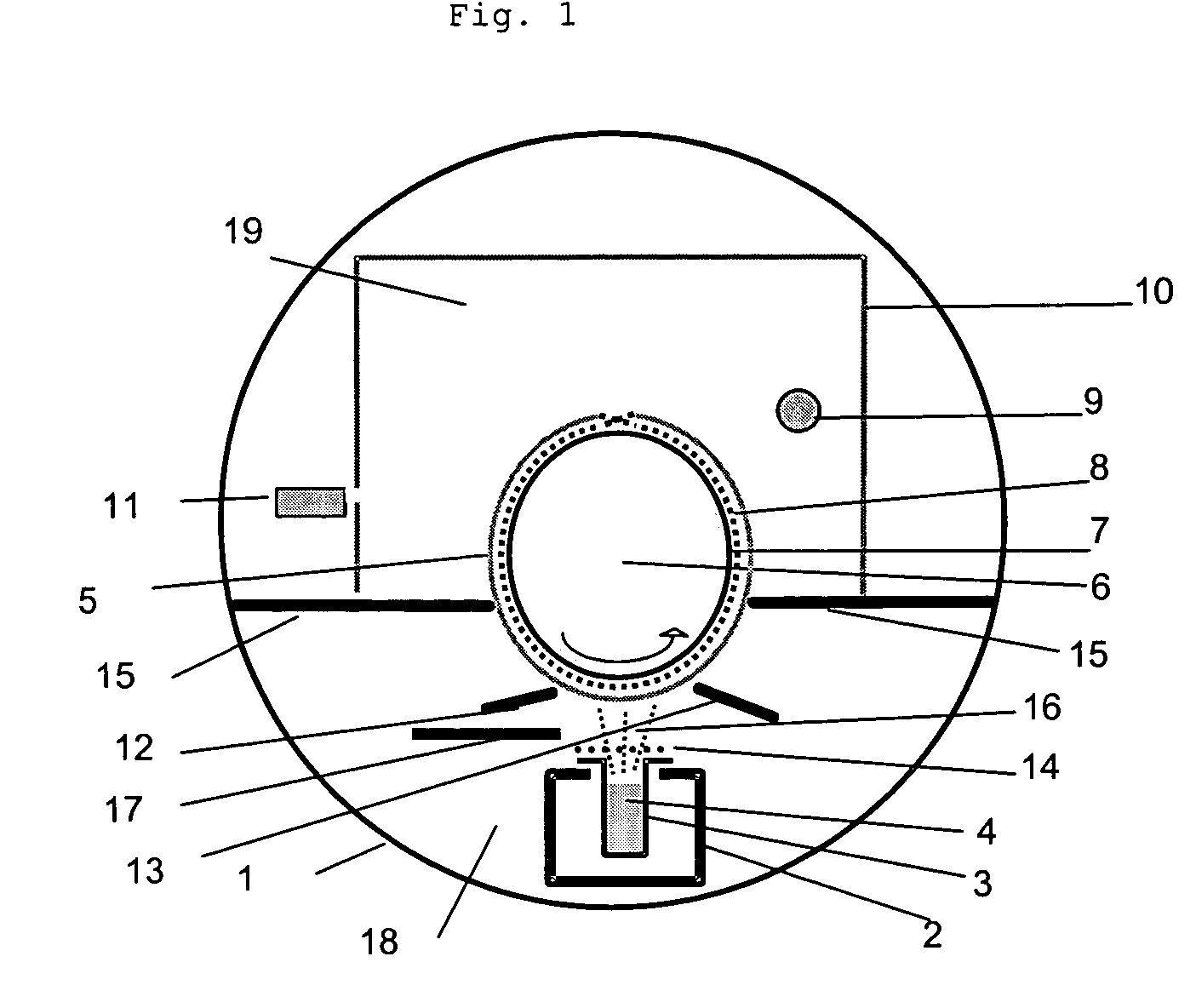
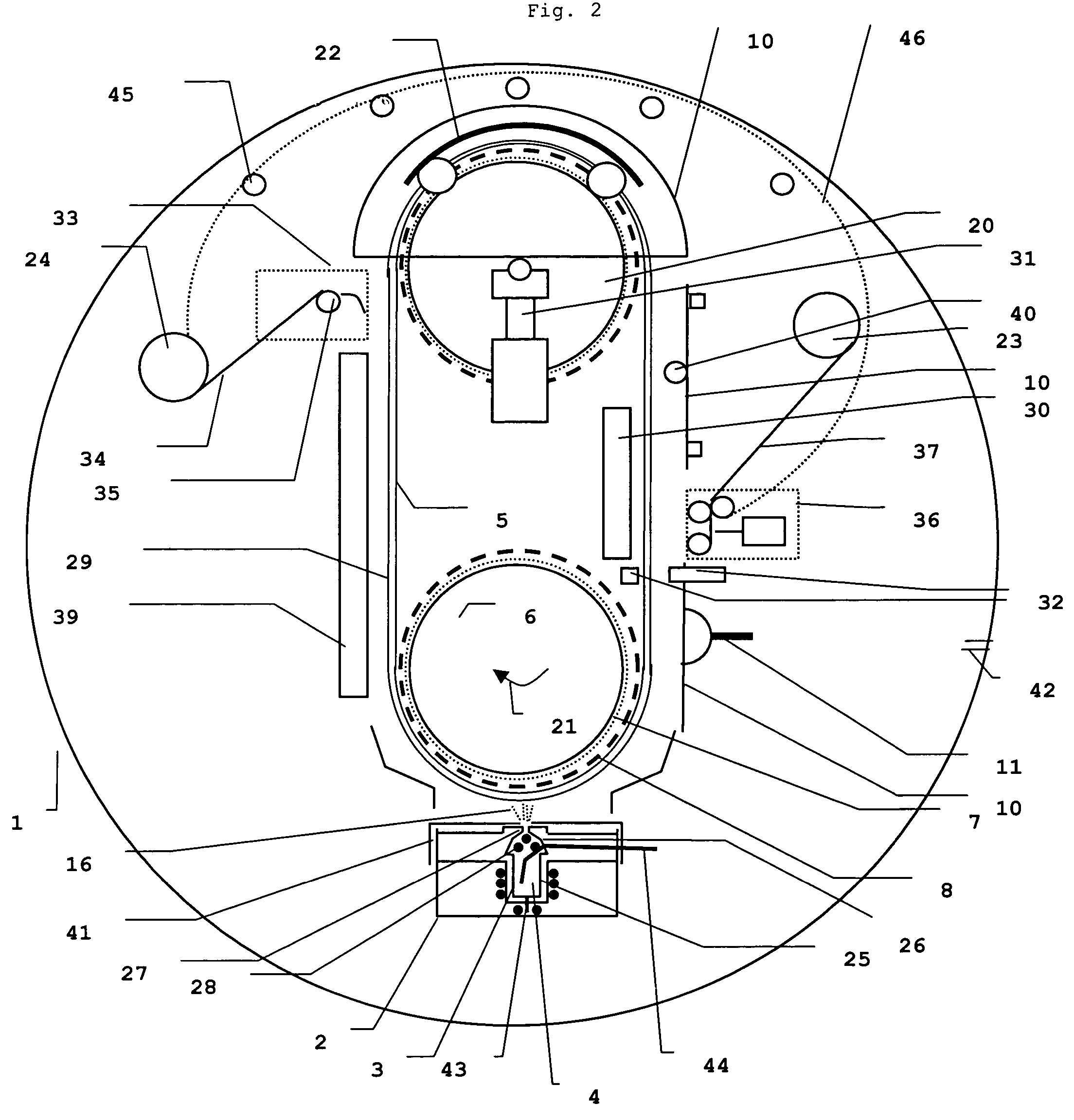
[0089]Referring to FIG. 2 the cylindrical vacuum chamber (1) with a diameter of 1.4 m and a length of 1.75 m was containing an electrically heated oven (2) and a refractory tray or boat (3) in which 4 kg of a mixture (4) of CsBr and EuOBr as raw materials in a 99.5% / 0.5% CsBr / EuOBr percentage ratio by weight were present to become vaporized.

[0090]Crucible (3) was an elongated boat composed of “tantalum” having a thickness of 0.5 mm composed of 3 parts: a crucible container (25), an internally heated chimney (26) and a controllable outlet (2...

example 2

[0107]Same experiments were performed as in the inventive Example 1, except for the temporary protection, after the deposition of the needle-shaped phosphor imaging layer, by a laminate, provided by lamination of said imaging layer in vacuum. In this way the material was protected in order to be safely moved out of the vacuum chamber. The material could also be cut in the presence of the laminate so that contamination with debri or dust was made impossible. After cutting, the temporary protection laminate was removed by delamination. During delamination, debri or dust, present on the cutting edges, stuck to the laminate and did not contaminate the material.

example 3

[0108]Same experiments were performed as in the inventive Example 1, except for the protection, after the deposition of the needle-shaped phosphor imaging layer, by a laminate, provided by lamination in vacuum of said imaging layer with a lasting protection layer, originating from a lamination package. In this experiment the lamination package was consisting of a siliconized polyethylene terephthalate release layer, an adhesive layer and the protection foil. The lamination package was passing the laminate unit (36) with mechanism for supplying laminate foil and the protective foil was delaminated from the release layer (siliconized polyethylene terephthalate) to become laminated onto the vapor deposited phosphor layer. As this operation proceeded in vacuum the phosphor layer was remaining dust free. The release layer was further guided over the guiding rollers (45) to the same delamination collecting roller as used for delamination of the initial laminate present on the protected su...


PUM

PropertyMeasurementUnit
thicknessaaaaaaaaaa
thicknessaaaaaaaaaa
thicknessaaaaaaaaaa

Abstract

In a method for homogeneously and dust-free coating of a phosphor or a scintillator layer onto a flexible substrate, in order to obtain a plurality of phosphor or scintillator sheets or panels having flexible supports or substrates, a coating procedure within a sealed zone is performed, wherein said zone comprises at least two cylindrical carrier rollers for carrying a flexible substrate exceeding dimensional formats of desired phosphor or scintillator sheets or panels with a factor of at least 5, wherein said cylindrical carrier rollers each have an axis in a parallel arrangement with one another; wherein said zone comprises at least one crucible containing a mixture of raw materials providing desired phosphor or scintillator compositions for said layer; and wherein said zone comprises a laminating unit; wherein said method comprises the steps of mounting said flexible substrate onto said carrier rollers, vapor depositing said phosphor or scintillator layer having a desired phosphor or scintillator composition onto said flexible substrate, and laminating said phosphor or scintillator layer, thereby covering said layer with a protective foil; further comprising the step of cutting said layer into sheets or panels having desired formats, and wherein at least during said vapor depositing step said zone is maintained under vacuum conditions as a vacuum chamber.

Description

FIELD OF THE INVENTION[0001]The present invention relates to a particular method of continuously, on-line coating of a layer from a vapor flow of raw materials on a flexible substrate. More particularly the present invention relates to the manufacturing or production of scintillator or phosphor sheets, used in screens, panels or plates suitable for use in high energy radiation detection and imaging and, more particularly, in computed radiography, screen / film radiography and direct radiography.BACKGROUND OF THE INVENTION[0002]In radiography the interior of objects is reproduced by means of penetrating radiation, which is high energy radiation also known as ionizing radiation belonging to the class of X-rays, γ-rays and high-energy elementary particle rays, e.g. β-rays, electron beam or neutron radiation.[0003]For the conversion of penetrating radiation into visible light and / or ultraviolet radiation “luminescent” substances, called “phosphors”, are used. Cathodoluminescent phosphors ...

Claims


Application Information

Patent Timeline
Patent Type & Authority Patents(United States)
IPC IPC(8): B32B37/00G21K4/00C01D3/10C09K11/00C09K11/08C09K11/61C09K11/77C23C14/06C23C14/24C23C14/50C23C14/54C23C14/56G01T1/00
CPCC09K11/7733C23C14/0694C23C14/243C23C14/541C23C14/562C23C14/505Y10T156/1944Y10T156/1052
Inventor GUIDO, VERREYKENPETER, BLUYSRUDY, HENDRICKXLUCAS, PEETERSJOHAN, LAMOTTE
Owner T2PHARMA GMBH
Why Eureka
Try Eureka