Method for forming plated terminations
a technology of plated terminations and plated strips, which is applied in the direction of piezoelectric/electrostrictive transducers, fixed capacitors, metallic pattern materials, etc., can solve the problems of difficult to print termination stripes in a predetermined area with required precision, difficult to control the application of terminations, and reduce the size of chips, so as to eliminate or greatly simplify thick-film stripes. , the effect of improving the termination featur
- Summary
- Abstract
- Description
- Claims
- Application Information
AI Technical Summary
Benefits of technology
Problems solved by technology
Method used
Image
Examples
embodiment 16
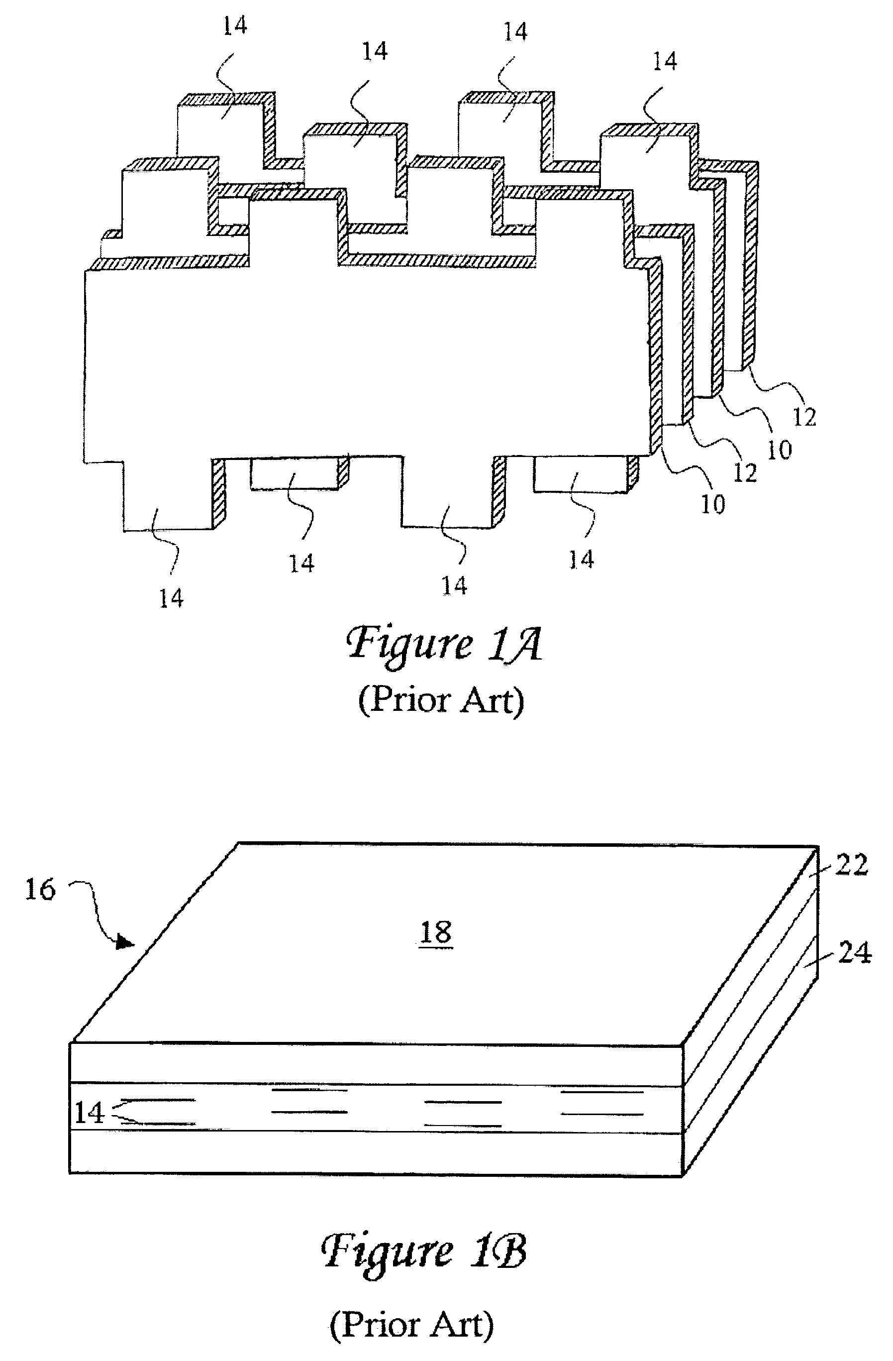
[0057]An interdigitated capacitor typically consists of a plurality of electrode layers, such as those shown in FIG. 1A disposed in a body of dielectric material 18, such as seen in the exemplary interdigitated capacitor configuration 16 of FIG. 1B. Electrode layers 10 and 12 are disposed in the dielectric material 18 such that electrode tabs 14 extend to and are exposed at two sides of IDC embodiment 16. Exemplary materials for such electrode layers may include platinum, nickel, a palladium-silver alloy, or other suitable conductive substances. Dielectric material 18 may comprise barium titanate, zinc oxide, alumina with low-fire glass, or other suitable ceramic or glass-bonded materials. Alternatively, the dielectric may be an organic compound such as an epoxy (with or without ceramic mixed in, with or without fiberglass), popular as circuit board materials, or other plastics common as dielectrics. In these cases the conductor is usually a copper foil which is chemically etched to...
embodiment 74
[0072]There are several different techniques that can potentially be used to form plated terminations, such as terminations 72 on multilayer component embodiment 74 of FIG. 8A. As previously addressed, a first method corresponds to electroplating or electrochemical deposition, wherein an electronic component with exposed conductive portions is exposed to a plating solution such as electrolytic nickel or electrolytic tin characterized by an electrical bias. The component itself is then biased to a polarity opposite that of the plating solution, and conductive elements in the plating solution are attracted to the exposed metallization of the component. Such a plating technique with no polar biasing is referred to as electroless plating, and can be employed in conjunction with electroless plating solutions such as nickel or copper ionic solution.
[0073]In accordance with electrochemical deposition and electroless plating techniques, a component such as IDC 74 of FIG. 8A, is preferably s...
PUM
| Property | Measurement | Unit |
|---|---|---|
| thickness | aaaaa | aaaaa |
| thickness | aaaaa | aaaaa |
| size | aaaaa | aaaaa |
Abstract
Description
Claims
Application Information
 - R&D
- Intellectual Property
- Life Sciences
- Materials
- Tech Scout
- Unparalleled Data Quality
- Higher Quality Content
- 60% Fewer Hallucinations
Browse by: Latest US Patents, China's latest patents, Technical Efficacy Thesaurus, Application Domain, Technology Topic, Popular Technical Reports.
© 2025 PatSnap. All rights reserved.Legal|Privacy policy|Modern Slavery Act Transparency Statement|Sitemap|About US| Contact US: help@patsnap.com


