
Plasma processing apparatus and method of plasma processing

a plasma processing apparatus and plasma technology, applied in the field of plasma processing apparatus and plasma processing method, can solve the problems of insufficient conventional conditions for etching of oxide films, insufficient effort to remove and insufficient effort to achieve the above described non-uniform electric field distribution. to achieve the effect of preventing standing waves

Inactive Publication Date: 2006-12-26
TOKYO ELECTRON LTD
View PDF12 Cites 16 Cited by
  • Summary
  • Abstract
  • Description
  • Claims
  • Application Information

AI Technical Summary

Benefits of technology

[0012]The present invention has been made in view of such circumstances. It is an object of the present invention to provide a plasma processing system and method capable of decreasing the non-uniformity of an electric field distribution on the surface of an electrode and making the density of plasma uniform, in a plasma processing using a high density plasma capable of coping with a further scale down.
[0019]According to the present invention, a substrate to be processed is arranged in a processing space between first and second elements which are provided so as to face each other. By supplying a high frequency electric power to the first electrode while feeding a process gas to the processing space, plasma is formed in the processing space to plasma-process the substrate. When the high frequency electric power is fed to the opposite surface to a surface of the first electrode facing the second electrode to form plasma, the feeding position is moved on the feeding plane. Therefore, no interference is caused unlike a case where a high frequency electric power is fed from the center of the electrode, so that it is possible to prevent standing waves caused by the interference action from being formed. For example, by shifting and rotating the feeding position from the center of the electrode, a position at which the field intensity is high moves, so that the field intensity is equalized. Therefore, the field distribution on the plasma contact surface of the first electrode can be uniform, so that the density of plasma can be uniform.

Problems solved by technology

However, in recent years, the scale down of the design rule for ULSIS is increasingly advancing, and a higher aspect ratio of a hole shape is required, so that conventional conditions are not always sufficient in etching of an oxide film and so forth.
By the way, according to the results of the inventor's study, it was revealed that there was the following new problem when the frequency of the high frequency electric power to be applied was raised to increase the density of plasma.
Therefore, standing waves are formed on the plasma contact surface of the top electrode due to the interference action, so that the electric field distribution is non-uniform in radial directions of the electrode.
However, conventionally, such problems caused by using the high density plasma have not been always recognized, and it has not sufficiently attempted to remove the above described non-uniformity of the electric field distribution in the present circumstances.

Method used


Image

  • Plasma processing apparatus and method of plasma processing
  • Plasma processing apparatus and method of plasma processing
  • Plasma processing apparatus and method of plasma processing

Examples


Embodiment Construction

[0029]Referring now to the accompanying drawings, the preferred embodiments of the present invention will be described below.

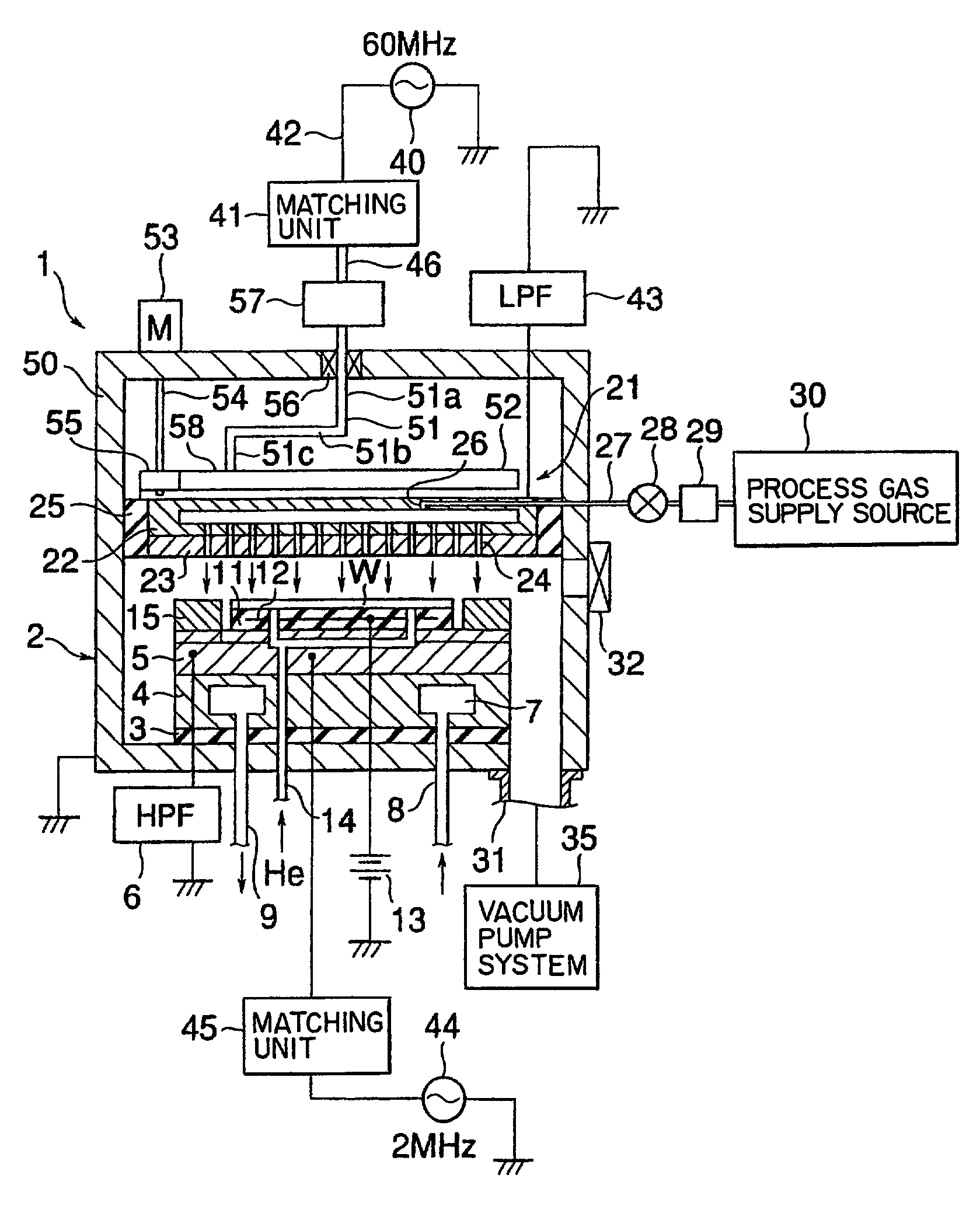
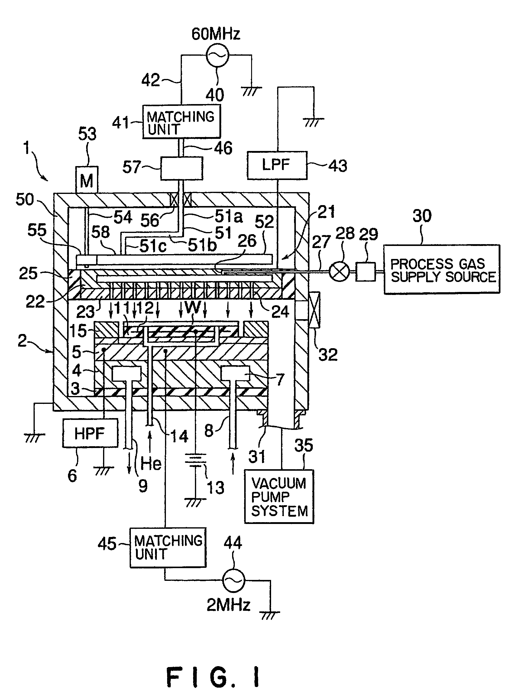
[0030]First, the first preferred embodiment of the present invention will be described. FIG. 1 is a sectional view schematically showing the first preferred embodiment of a plasma processing system according to the present invention. This plasma processing system 1 is a capacitive coupled parallel plate etching system wherein top and bottom electrode plates face each other in parallel to each other and wherein a plasma forming power supply is connected to one of the electrodes.

[0031]The plasma etching processing system 1 has a cylindrical chamber 2 of aluminum, the surface of which is anodized. This chamber 2 is safety-grounded. A substantially cylindrical susceptor supporting table 4 for mounting thereon an object to be processed, e.g., a semiconductor wafer (which will be hereinafter referred to as a “wafer”) W, is provided on the bottom in the chamber 2 via...


PUM

PropertyMeasurementUnit
dc voltageaaaaaaaaaa
pressureaaaaaaaaaa
frequencyaaaaaaaaaa

Abstract

There is provided a plasma processing system and method capable of decreasing the non-uniformity of a field distribution on the surface of an electrode and making the density of plasma uniform, in a plasma processing using a high density plasma which can cope with a further scale down. First and second electrodes 21 and 5 are provided in a chamber so as to face each other. A feeder plate 52 is arranged so as to be slightly spaced from the opposite surface of a surface serving as a feeding plane of the first electrode facing the second electrode 5. A feeder rod 51 is connected to the feeder plate 52 at a position which is radially shifted from a position corresponding to the center of the feeding plane of the first electrode 21. The feeder plate 52 is rotated to rotate the feeding position of the feeder rod 51 on the feeding plane of the first electrode. A high frequency electric power is thus fed to form a high frequency electric field between the first and second electrodes 21 and 5 to form plasma to plasma-process a substrate W.

Description

TECHNICAL FIELD[0001]The present invention relates generally to a plasma processing system and method for plasma-processing a substrate, such as a semiconductor substrate.BACKGROUND ART[0002]For example, in a process for producing semiconductor devices, various plasma processes, such as etching, sputtering and CVD (chemical vapor deposition), are used for processing semiconductor wafers serving as substrates to be processed.[0003]As plasma processing systems for carrying out such plasma processes, various systems are used. Among these systems, capacitive coupled parallel plate plasma processing systems are mainly used.[0004]The capacitive coupled parallel plate plasma processing system has a pair of parallel plate electrodes (top and bottom electrodes) in a chamber. This system is designed to introduce a process gas into the chamber and to apply high-frequency electric power to one of the electrodes to form a high frequency electric field between the electrodes to form plasma of the...

Claims


Application Information

Patent Timeline
Patent Type & Authority Patents(United States)
IPC IPC(8): H01L21/00H01L21/302B01J19/08C23C16/52H01J37/32H01L21/3065H05H1/46
CPCH01J37/32082H01J37/3244H01J37/32568H01J37/32577H01L21/3065
Inventor TOMOYASU, MASAYUKI
Owner TOKYO ELECTRON LTD
Features
  • Generate Ideas
  • Intellectual Property
  • Life Sciences
  • Materials
  • Tech Scout
  • Unparalleled Data Quality
  • Higher Quality Content
  • 60% Fewer Hallucinations
Learn More