Device and method for generating a local by micro-structure electrode dis-charges with microwaves

a micro-structure electrode and microwave technology, applied in plasma techniques, gas-filled discharge tubes, energy-based chemical/physical/physico-chemical processes, etc., can solve the problem that high-frequency or microwave excitations have not been implemented under known methods

Inactive Publication Date: 2007-01-09
ROBERT BOSCH GMBH
View PDF6 Cites 11 Cited by
  • Summary
  • Abstract
  • Description
  • Claims
  • Application Information

AI Technical Summary

Benefits of technology

[0005]It is believed that the device in accordance with the present invention and its associated method have the advantage over the related art of eliminating the need for the produced plasma to come into direct contact with the device producing the plasma, and, in particular, with the parts of this device being used as electrodes. This may substantially prolong the service life of the entire device in accordance with the present invention and, in particular, of the guide structure being used as microstructure electrodes. Moreover, the device in accordance with the present invention may be easier to service.
[0011]As part of the device for generating the gas discharge and, respectively, the plasma, the guide structure for the injected microwaves is in an exemplary embodiment a metallic waveguide, which is filled with a puncture-proof, rigid dielectric material, such as silicon dioxide. However, in an alternative exemplary embodiment, the guide structure can be constructed of an arrangement of at least two, preferably parallel spaced metal plates, whose interstitial space is filled in with a dielectric material. Due to its simpler structural design, as compared to closed waveguides, this configuration may offer advantages from a standpoint of production engineering.
[0013]A particular benefit is derived when the H10 mode of the launched microwaves is excited and guided in the waveguide, as a guide structure, since, in this case, it is merely the width of the waveguide that is critical for the propagation of the microwaves, and its length, for example, apart from unavoidable attenuation, can be varied substantially freely.
[0016]It is quite beneficial for these plasma regions to be cylindrical holes in the guide structure. Typical cylindrical hole diameters are advantageously about 50 μm to 1000 μm. They are expediently distributed in a regular arrangement in the vicinity of the guide structure. In the case of a waveguide as a guide structure, these cylindrical holes have the considerable advantage, in combination with the excited H10 mode, that the generated electrical field is aligned within the waveguide in parallel to the cylindrical holes and is substantially homogeneous. As a result, variations in field strength in the direction of the waveguide width are minimal in comparison to higher excitable modes.
[0017]To avoid or minimize surface stress or material ablation and accompanying gradual destruction of the plasma regions (i.e., of the guide structure) by the generated plasma, the inner wall of the cylindrical holes and, optionally, the entire electrode surfaces as well, are advantageously provided with a dielectric, in particular a ceramic protective layer. This dielectric protective layer only marginally degrades the propagation of the microwaves in the guide structure.
[0019]The supplied gas is preferably an inert gas, in particular argon, He or Xe, as well as air, nitrogen, hydrogen, acetylene or methane, that is preferably supplied with a gas flow of about 10 scam to about 1000 scam (standard cubic centimeters per minute). However, in the individual case, these parameters are scaled by the selected dimensional size of the device for producing plasma and are merely to be considered as typical values. Another significant benefit is that the device in accordance with the present invention can be operated while exposed to air, thereby achieving an oxidic surface excitation. Moreover, the broad pressure range within which the work can be done, from atmospheric pressure down to a precision vacuum, makes possible many diverse applications.

Problems solved by technology

High-frequency or microwave excitations have not been implemented under known methods heretofore.

Method used


Image

  • Device and method for generating a local by micro-structure electrode dis-charges with microwaves
  • Device and method for generating a local by micro-structure electrode dis-charges with microwaves

Examples


Embodiment Construction

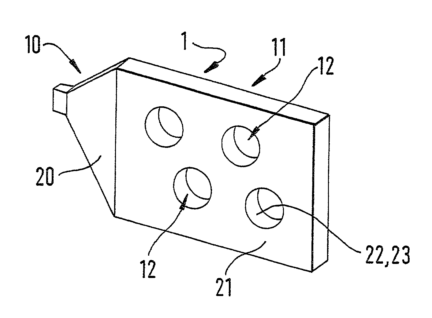
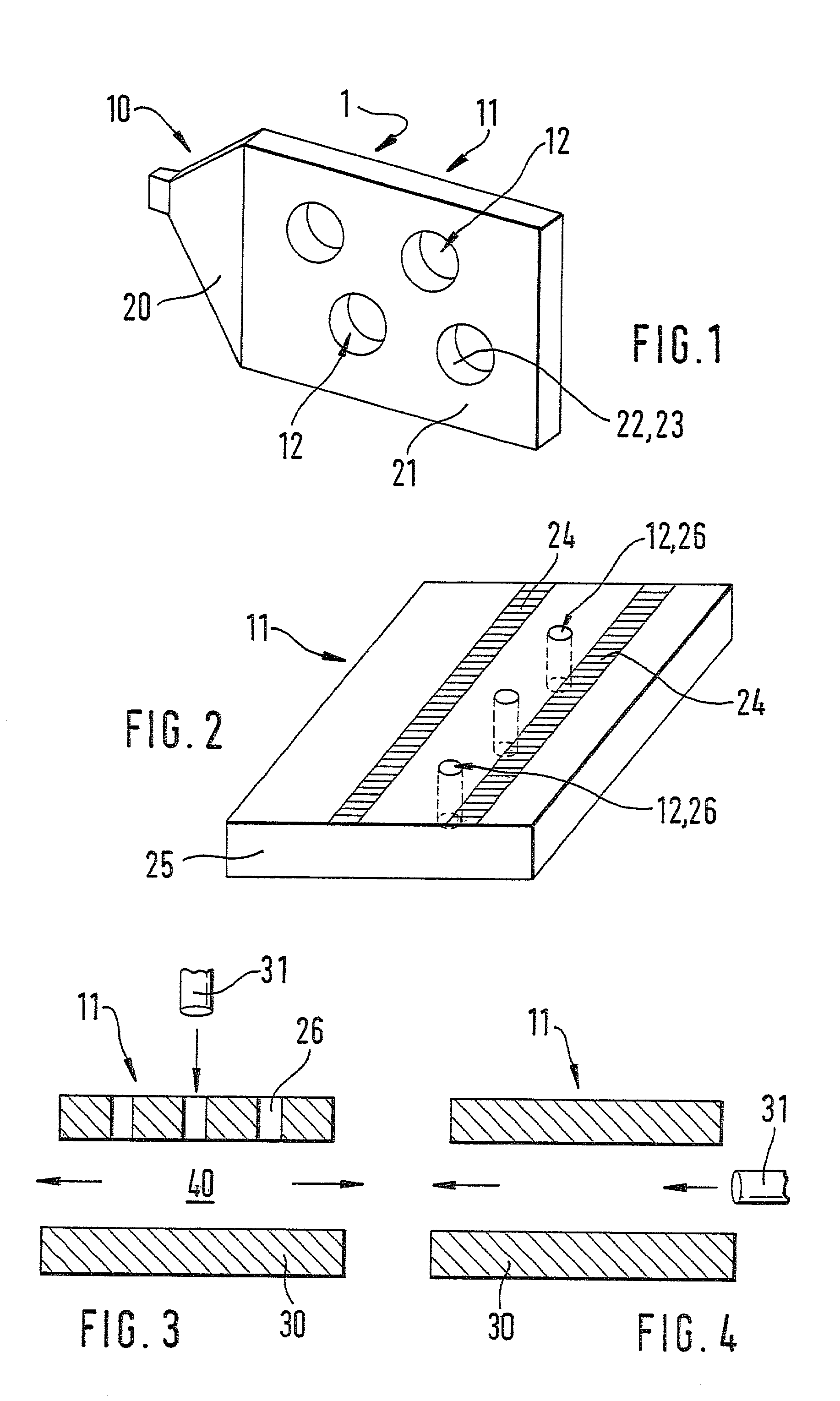
[0025]FIG. 1 illustrates a device 1 having a launching structure 10, a guide structure 11, and plama regions 12. In this case, launching structure 10 has the shape of a horn 20, as is generally known from microwave technology, and is used for launching microwaves into guide structure 11. The microwaves are generated by a generally known microwave generator (not shown) which is linked to launching structure 10. Horn 20 passes electroconductively over into guide structure 11, enabling microwaves to be launched by microwave generator via launching structure 10 into guide structure 11.

[0026]In this example, guide structure 11 is designed as waveguide 21 of a metal, such as copper, high-grade steel, gold or silver, which is filled on the inside, for example, with silicon dioxide as rigid, puncture-proof, low-loss dielectric material 22. Waveguide 21 has a thickness of up to a few mm. Its length is variable, but should amount to one fourth of the wavelength of the injected microwaves. Its...


PUM

PropertyMeasurementUnit
distanceaaaaaaaaaa
frequencyaaaaaaaaaa
frequencyaaaaaaaaaa

Abstract

Device for producing a plasma, in particular for treating surfaces, for chemically reacting gases, or for producing light, by way of microstructure electrode discharges, using a device for producing plasma having at least one guide structure. A microwave generator which can be used to launch microwaves into the guide structure. The guide structure has a locally narrowly limited plasma region in contact with a gas. The guide structure is preferably a metallic waveguide filled with a dielectric material, or an arrangement of strip lines which run on a dielectric plate. The device and the method are particularly suited for processing or activating surfaces or for depositing layers on a substrate.

Description

FIELD OF THE INVENTION[0001]The present invention relates to a device and a method for producing a plasma, in particular for treating surfaces, for chemically reacting gases, or for producing light, by making use of microstructure electrode discharges.BACKGROUND INFORMATION[0002]When treating surfaces using a plasma method, it is advantageous for the plasma to be produced as closely as possible to the surface or substrate to be treated, or for a plasma source having a sharply defined or local plasma volume to be introduced in close proximity to the substrate to be treated. This may be achieved by using so-called microstructure electrode discharges, provision being made for dielectric plates having electrodes that are typically disposed at a distance of approximately 100 μm or less from one another. As is generally known, discharges of this kind work within a very broad pressure range and exhibit relatively sharply delimited plasma interfaces, i.e., large-area, but locally narrowly l...

Claims


Application Information

Patent Timeline
Patent Type & Authority Patents(United States)
IPC IPC(8): C23C16/511H05H1/46B01J19/08H01J37/32H05H1/24
CPCH01J37/32192H05H1/24H01J37/32596H05H1/46H05H1/4622
Inventor GROSSE, STEFANVOIGT, JOHANNES
Owner ROBERT BOSCH GMBH
Why Eureka
Try Eureka