Carbon nanotube array and method for forming same

a carbon nanotube and array technology, applied in the direction of carbonsing rags, aligned nanotubes, chemistry apparatus and processes, etc., can solve the problems of decomposing the carbon source gas to form amorphous carbon, affecting the and generally impairing the high-density formation of pure, straight carbon nanotubes

Active Publication Date: 2007-01-09
TSINGHUA UNIV +1
View PDF11 Cites 124 Cited by
  • Summary
  • Abstract
  • Description
  • Claims
  • Application Information

AI Technical Summary

Benefits of technology

[0007]However, carbon nanotube arrays are generally formed on nonmetallic substrates such as silicon, silicon oxide or glass. This is because metal substrates generally impair high-density formation of pure, straight carbon nanotubes. In particular, a metal substrate is liable to react with the nanotube catalyst to form an alloy thereof, which renders the catalyst inactive. In addition, when the metal substrate itself is the catalyst, it is prone to decompose the carbon source gas to form amorphous carbon. Amorphous carbon inhibits formation of carbon nanotubes of the desired quality. In summary, it is difficult to optimally form carbon nanotubes using metal substrates.

Problems solved by technology

This is because metal substrates generally impair high-density formation of pure, straight carbon nanotubes.
In particular, a metal substrate is liable to react with the nanotube catalyst to form an alloy thereof, which renders the catalyst inactive.
In addition, when the metal substrate itself is the catalyst, it is prone to decompose the carbon source gas to form amorphous carbon.
In summary, it is difficult to optimally form carbon nanotubes using metal substrates.
However, this method does not provide original formation of carbon nanotubes directly on the metal substrate.
In addition, when said water-soluble gel is allowed to settle, the time required is unduly long: typically around one month.
These difficulties greatly limit industrial applications of the carbon nanotube assembly and method.
This limitation is necessary to prevent the metal substrate from adversely affecting formation of the carbon nanotubes by reacting with the catalyst or by decomposing the carbon source gas to form amorphous carbon.
Accordingly, the method is generally limited to applications in which aluminum and nickel electronic devices can be utilized.

Method used


Image

  • Carbon nanotube array and method for forming same
  • Carbon nanotube array and method for forming same
  • Carbon nanotube array and method for forming same

Examples


Embodiment Construction

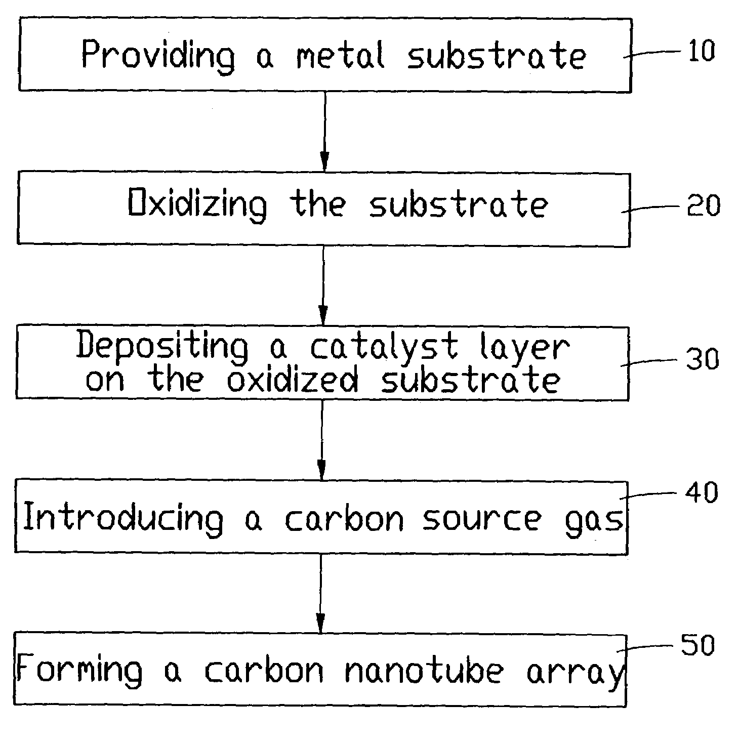
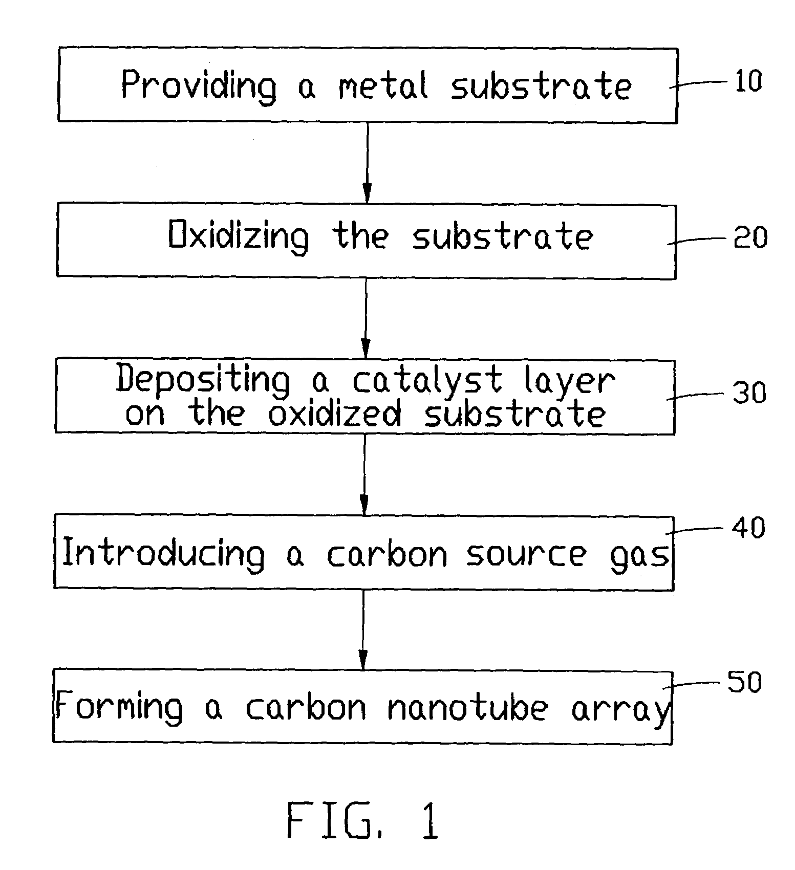
[0021]A preferred method for forming a carbon nanotube array using a metal substrate according to the present invention will be described with reference to the flowchart of FIG. 1.

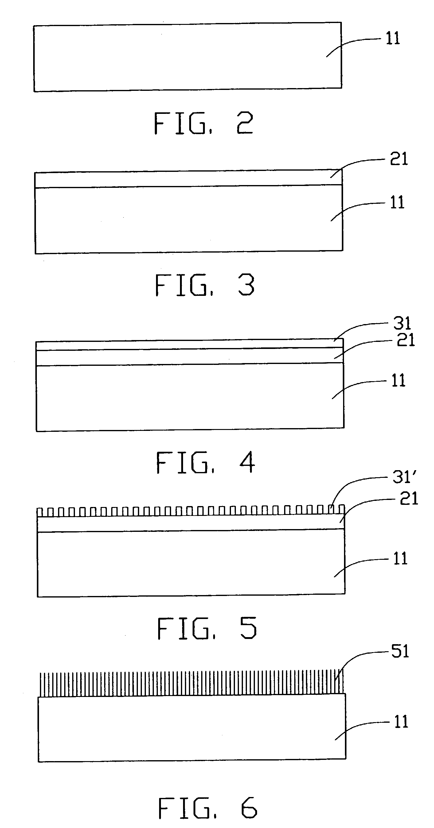
[0022]Referring also to FIGS. 2–6, a metal substrate 11 is first provided (step 10). The substrate 11 can be a metal plate or a metal electrode formed on a base. If a base is used, it can be glass, silicon, quartz or another suitable material having a smooth surface. The metal electrode can be formed on the base by plating or sputtering. The selected metal plate or metal electrode is polished to obtain a smooth surface thereon. The metal substrate 11 can be nickel (Ni), steel, tantalum (Ta), silver (Ag) or another suitable metallic material.

[0023]In principle, there is no particular limitation on selection of the metal plate material or the metal electrode material. Any metallic material used in the semiconductor industry can be used as the metal substrate 11. However, there are four criteria that must be ...


PUM

PropertyMeasurementUnit
thicknessaaaaaaaaaa
temperatureaaaaaaaaaa
thicknessaaaaaaaaaa

Abstract

A method for forming a carbon nanotube array using a metal substrate includes the following steps: providing a metal substrate (11); oxidizing the metal substrate to form an oxidized layer (21) thereon; depositing a catalyst layer (31) on the oxidized layer; introducing a carbon source gas; and thus forming a carbon nanotube array (61) extending from the metal substrate. Generally, any metallic material can be used as the metal substrate. Various carbon nanotube arrays formed using various metal substrates can be incorporated into a wide variety of high power electronic device applications such as field emission devices (FEDs), electron guns, and so on. Carbon nanotubes formed using any of a variety of metal substrates are well aligned, and uniformly extend in a direction substantially perpendicular to the metal substrate.

Description

BACKGROUND OF THE INVENTION[0001]1. Field of the Invention[0002]The present invention relates to carbon nanotube arrays and methods for forming them, and more particularly to carbon nanotube arrays formed on metal substrates and methods for forming said carbon nanotube arrays. This application relates to a contemporaneously filed application having the same title, the same applicant and the same assignee with the instant application.[0003]2. Description of Prior Art[0004]Carbon nanotubes are very small tube-shaped structures each having the molecular structure of a graphite sheet rolled into a tube. Carbon nanotubes produced by arc discharge between graphite rods were first discovered and reported in an article by Sumio Iijima entitled “Helical Microtubules of Graphitic Carbon” (Nature, Vol. 354, Nov. 7, 1991, pp. 56–58). Carbon nanotubes have excellent mechanical properties such as a high Young's modulus, a high elastic modulus, and low density. Carbon nanotubes also have excellent...

Claims


Application Information

Patent Timeline
Patent Type & Authority Patents(United States)
IPC IPC(8): D01C5/00D01F9/12C01B31/02D01F9/127
CPCB82Y30/00B82Y40/00C01B31/0233D01F9/1271Y10S977/842Y10S977/742Y10S977/843C01B2202/08C01B32/162
Inventor LIU, LIANGFAN, SHOUSHAN
Owner TSINGHUA UNIV
Why Eureka
Try Eureka