
Method for deriving methanol from waste generated methane and structured product formulated therefrom

a technology of waste generated methane and methanol, which is applied in the direction of ether preparation, oxygen-containing compound preparation, organic chemistry, etc., can solve the problems of unsatisfactory hundreds of efforts to stop, multi-step rather expensive way, and unsatisfactory stop efforts, etc., and achieves simple cheap separation and less capitol

Inactive Publication Date: 2007-01-09
RINNOVI
View PDF25 Cites 0 Cited by
  • Summary
  • Abstract
  • Description
  • Claims
  • Application Information

AI Technical Summary

Benefits of technology

"The patent proposes a technique to make methanol with less capital per unit by directly oxidizing methane to methanol using a stopping agent, such as phthalic anhydride, which is a cheap and readily available chemical. The process involves reacting methane with simple separations from nitrogen or other inerts and avoiding major compression. The use of phthalic anhydride as a stopping agent has been previously described, but this patent proposes a new method that involves reacting methane with copper and air to form phthalic anhydride and methanol. The process is economically viable and the conversion of the stopping agent to methanol is easy and cheap. The patent also describes the use of other dicarboxylic acids and phthalic acid as starting materials for making phthalic anhydride. Overall, the patent proposes a new technique for making methanol with improved efficiency and economics."

Problems solved by technology

But unfortunately, many hundreds of efforts to stop there have been unsatisfactory.
No adequate stopping has been set.
In a multi-step rather expensive way, mercury complexes have worked.
Economics for this have proved unattractive, but a second reaction preventing the oxidation pattern above functioned.

Method used


Image

  • Method for deriving methanol from waste generated methane and structured product formulated therefrom
  • Method for deriving methanol from waste generated methane and structured product formulated therefrom
  • Method for deriving methanol from waste generated methane and structured product formulated therefrom

Examples


example 1

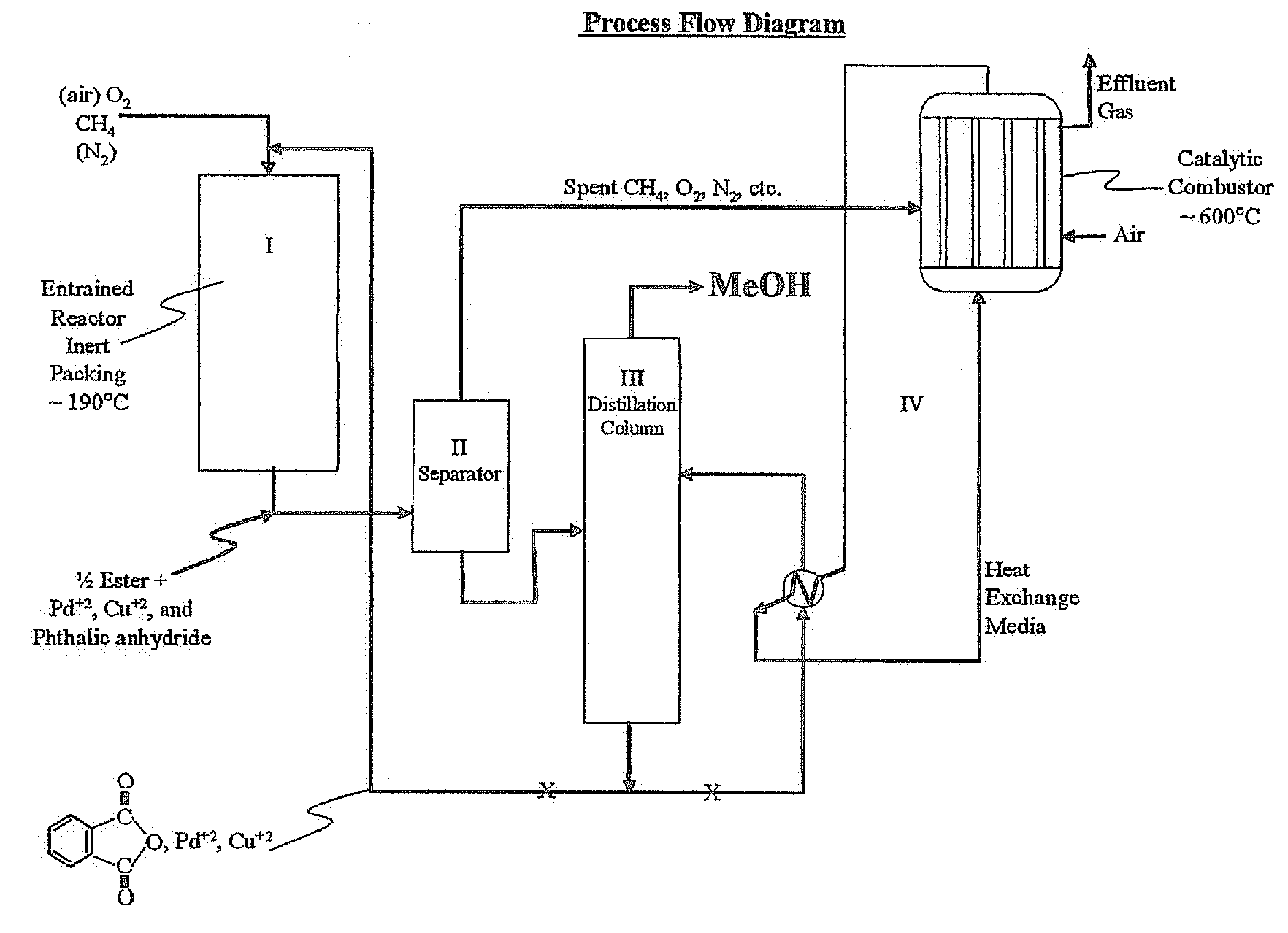
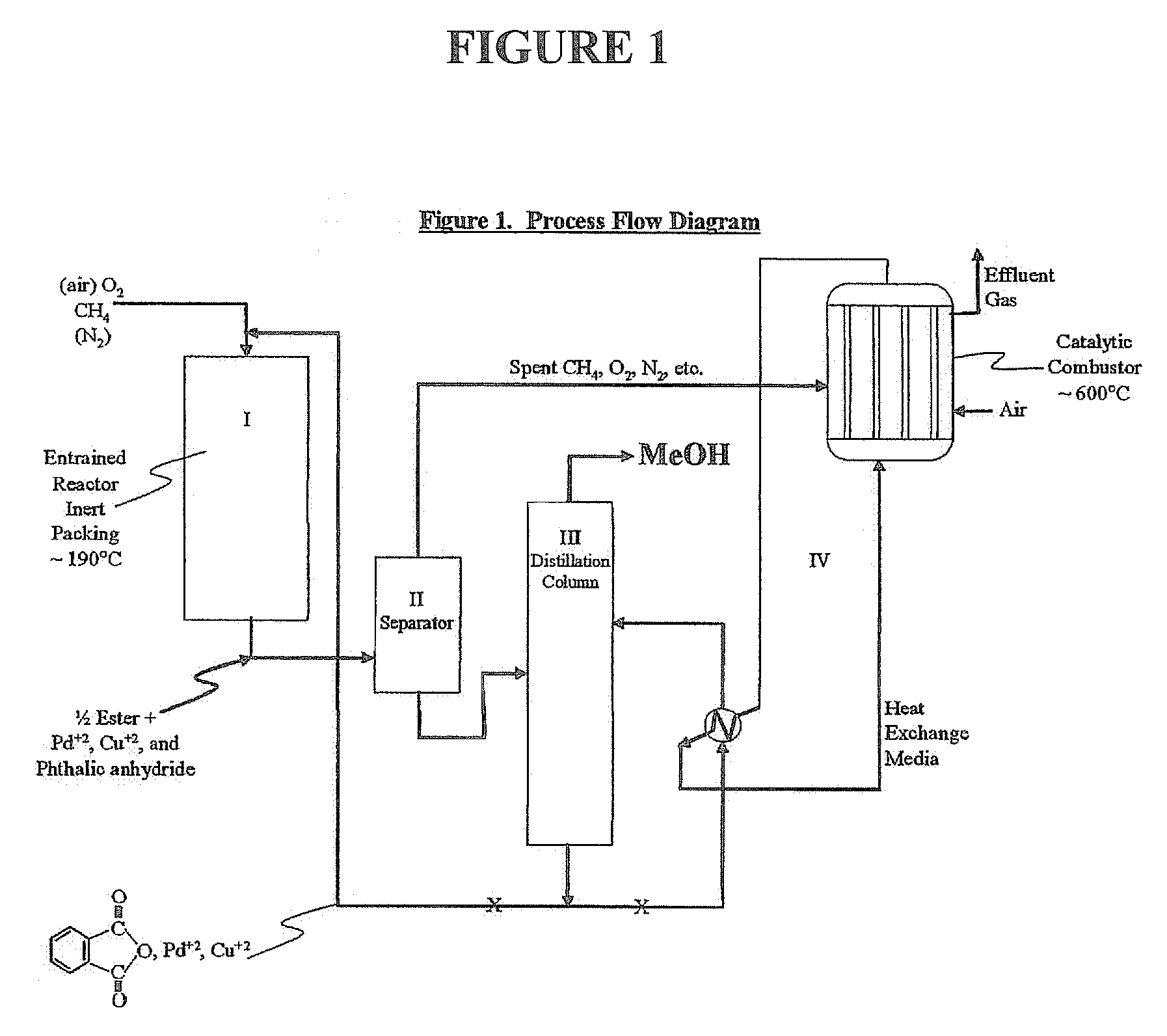
[0039]Utilizing the principles described in the summary, a waste methane input stream previously depleted of CO2 and sulfur containing gases is oxidized in an entrainment reactor utilizing molten phthalic anhydride as the solvent / reactant. Air is the source of oxygen for the system with nitrogen, carbon dioxide, and its minor components present. The waste methane input stream is derived from solid waste landfill bacterial decomposition and, as stated, has had carbon dioxide, hydrogen sulfide, methyl and ethyl mercaptan removed along with traces of higher mercaptans. The stream contains an average assay of 5% nitrogen. Oxidation takes place in the presence of 2% palladium and 2% copper phthalate in the phthalic anhydride solution.

[0040]Flow rates involve about 85% molten phthalic solution and the remainder entrained and dissolved air and methane. Air quantity is such that methane to oxygen ratio is maintained at 0.3 mol oxygen / mol methane. Contact time for the total mix of liquid and...

example 2

[0047]Essentially, the same as EXAMPLE 1, but with ¾ mullite inert ceramic spheres and super heated steam used as the heat exchange medium in the catalytic combustion of effluent from ethane oxidation in the phthalate system. Again, methanol is made as the product.

example 3

[0048]Same as EXAMPLE 1, except methane is not pre-treated to remove CO2 and any sulfur-containing components. Effluent will contain trace SO2 from the catalytic combustor and the feed gas CO2 as well as CO2, H2, N2, etc., from air plus effluent at ˜600° C. Product methanol will be essentially the same as EXAMPLE 1.


PUM

PropertyMeasurementUnit
pressureaaaaaaaaaa
pressureaaaaaaaaaa
pressureaaaaaaaaaa

Abstract

Methanol is produced from bacterially oxidized waste methane by reaction with Pd+2, Cu+2, air, and molten phthalic anhydride in an entrained oxidizer generating half ester of methyl phthalate which is reaction distilled to produce methanol and recycle phthalic anhydride containing the Pd+2, Cu+2 phthalate catalyst.

Description

CROSS REFERENCE TO RELATED APPLICATION[0001]This application claims the benefit of U.S. provisional application Ser. No. 60 / 683,040, filed May 20, 2005 the disclosure of which is incorporated herein by reference.BACKGROUND OF THE INVENTION[0002]Methanol manufacture from methane via methane to synthesis gas (CO+H2), and then synthesis gas to methanol is the current good, efficient, commercial way to make methanol. It becomes quite economic when performed on a big scale and using natural gas which is relatively free from inert non-hydrocarbon components. Conventional, small plants cannot compete well for capitol which becomes relatively high per unit of methanol produced. System pressure and need for compressors to raise pressure to 700–2500 psig is costly on a small scale. Today, methanol plants of over a billion pounds per year are desired. Whereas, 500 million pounds per year from waste methanol generation is about a maximum. Further, solid waste landfill assay gas will be about 50...

Claims


Application Information

Patent Timeline
Patent Type & Authority Patents(United States)
IPC IPC(8): C07C27/10C07C27/00C07C37/00C07C41/02
CPCC07C29/00C07C67/035C07C69/80C07C31/04
Inventor KNOX, LEGAL REPRESENTATIVE, CAROLKNOX, DECEASED, WALTER R.
Owner RINNOVI
Learn More