High resolution imaging fountain flow cytometry

a flow cytometry and high resolution technology, applied in the field of high resolution imaging fountain flow cytometry, can solve the problems of unsatisfactory sensitivity, high cost, and the like, and achieve the effects of high resolution, high throughput, and high resolution

Inactive Publication Date: 2007-01-09
UNIVERSITY OF WYOMING
View PDF6 Cites 76 Cited by
  • Summary
  • Abstract
  • Description
  • Claims
  • Application Information

AI Technical Summary

Benefits of technology

[0022]It is an object of the present invention to provide improved apparatus and methods for high throughput, high resolution imaging analysis of samples in a translucent flowing liquid. This object is accomplished by utilizing flow cytometry to first detect particles and then to reposition and magnify detected particles for high resolution imaging.
[0023]The present invention provides apparatus and methods for high throughput, high sensitivity imaging and classification of samples in a translucent or transparent flowing liquid. This object is accomplished by providing a relatively large cross section axial flow, in which cells or other target particles suspended in a liquid are observed as they are quickly passed through a tube oriented generally along the optical axis of imaging optics. When a rare cell of interest is detected, it is slowly passed back through the tube and imaged. This allows for real time high resolution imaging of rare cells, including multi-spectral imaging, without having to resort to labor-intensive microscopy or more complex and expensive MSIFC.
[0024]The present invention has advantages over Multi-Spectral Imaging Flow Cytometry (MSIFC), including detection of individual cells, at a much lower complexity, and thus cost. This invention is especially useful for real-time imaging of rare cells in a sample flow. This invention is based on taxonomic identification using fluorescent dyes.
[0027]1) By using several computer selectable parfocal objective lenses the user can image the entire field of view and then zoom in on a particular cell at substantially higher resolution.

Problems solved by technology

Cell imaging and classification systems developed to date usually suffer from 1) high cost, 2) unsatisfactory sensitivity, 3) slowness, 4) large size, 5) insufficient spectral and / or spatial resolution, and / or 6) labor-intensive preparation steps.
Small diameter orifices are generally unworkable because they experience frequent clogging.
Historically, flow cytometers have been very large, expensive, laboratory-based instruments.
They consume large amounts of power, and use complex electronics.
The size (desktop at the smallest), power requirements, and susceptibility to clogging (requiring operator intervention) of conventional flow cytometers precludes their use for many applications, such as field monitoring of water biocontamination.
Although this invention does not suffer from the drawbacks listed above for alternative technologies, it is not suitable for applications where the flow medium is not transparent.
The main disadvantage of this technique is that it requires TDI as well as conventional flow cytometry with all of its complexities including a hydrodynamically focused sheath flow.

Method used


Image

  • High resolution imaging fountain flow cytometry
  • High resolution imaging fountain flow cytometry
  • High resolution imaging fountain flow cytometry

Examples


Embodiment Construction

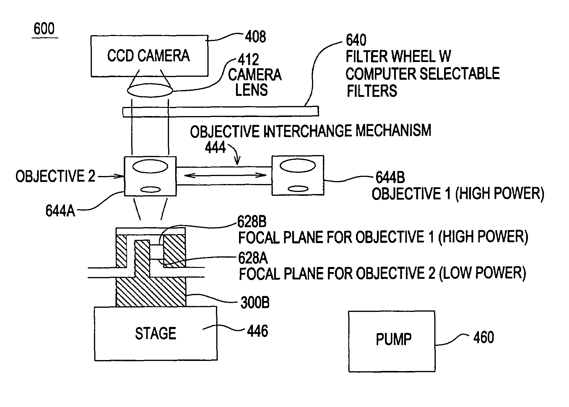
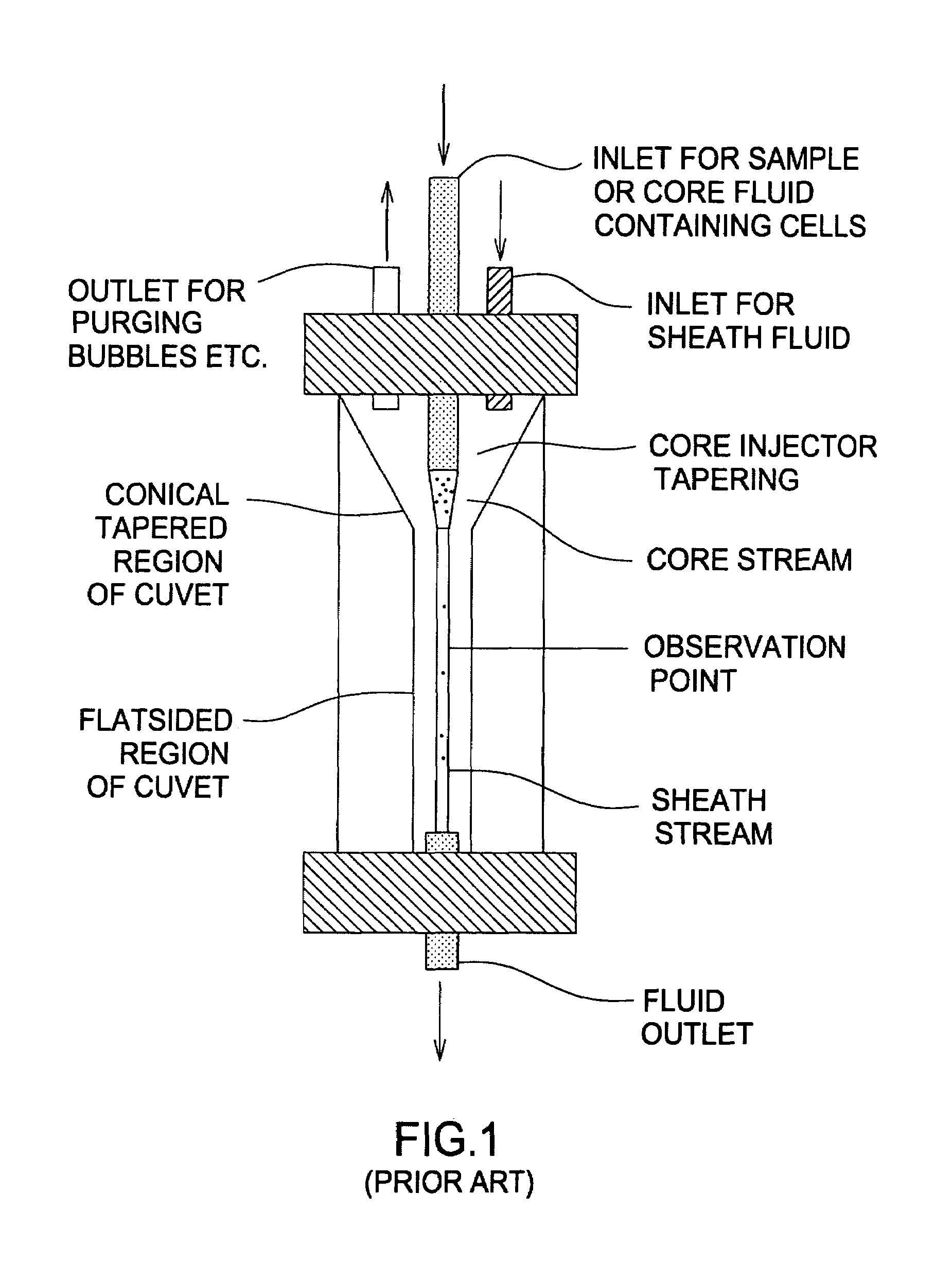
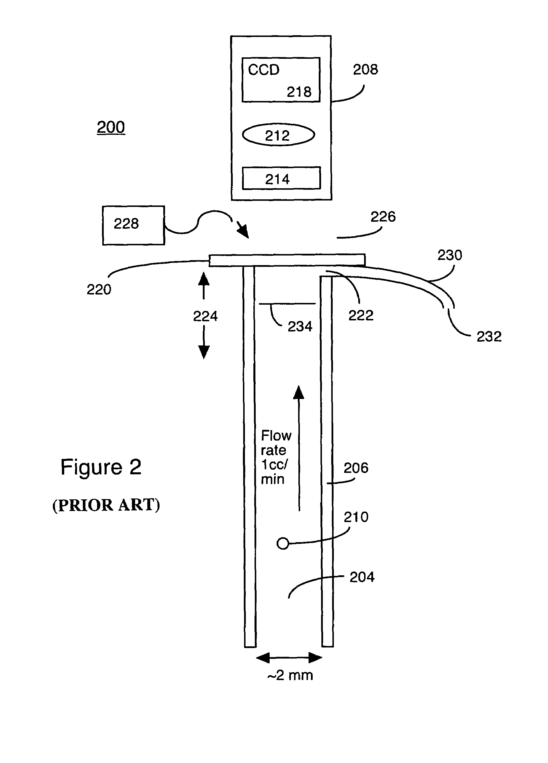
[0047]The present invention includes apparatus and methods for high resolution imaging of fluorescent particles in a fountain flow cytometry set up. (A precursor invention, described in U.S. patent application Ser. No. 10 / 323,535 by the present inventor, is shown in Prior Art FIGS. 2 and 3. This previous invention incorporates detection, but not high resolution imaging.) To review the flow cytometry detection process, a flow channel defines a flow direction for samples in a flow stream and has a viewing plane nearly perpendicular to the flow direction. A clear volume between the illuminated flow volume and the imaging optics is provided in some embodiments. A beam of illumination is formed as a column having a size that can effectively cover the viewing plane, and illuminates the flow end on or nearly end on. Imaging optics are arranged to view the focal plane to form a low-resolution image of the multiple fluorescent sample particles in the flow stream. In this step, particles of i...


PUM

PropertyMeasurementUnit
diameteraaaaaaaaaa
distanceaaaaaaaaaa
transparentaaaaaaaaaa

Abstract

An imaging fountain flow cytometer allows high resolution microscopic imaging of a flowing sample in real time. Cells of interest are in a vertical stream of liquid flowing toward one or more illuminating elements at wavelengths which illuminate fluorescent dyes and cause the cells to fluoresce. A detector detects the fluorescence emission each time a marked cell passes through the focal plane of the detector. A bi-directional syringe pump allows the user to reverse the flow and locate the detected cell in the field of view. The flow cell is mounted on a computer controlled x-y stage, so the user can center a portion of the image on which to zoom or increase magnification. Several computer selectable parfocal objective lenses allow the user to image the entire field of view and then zoom in on the detected cell at substantially higher resolution. The magnified cell is then imaged at the various wavelengths.

Description

[0001]This application is a Continuation in Part of U.S. patent application Ser. No. 10 / 323,535, filed Dec. 18, 2002 now U.S. Pat. No. 6,765,656, and incorporates that application by reference.BACKGROUND OF THE INVENTION[0002]1. Field of the Invention[0003]The present invention relates to apparatus and methods for high resolution imaging and classification of sample particles in translucent or transparent flowing liquid. In particular, the present invention relates to high throughput analysis of imaged particles in a translucent flow.[0004]2. Description of the Prior Art[0005]Imaging and classification of low concentrations of selected target particles, cells in particular, in large volumes of fluid has a number of applications including: 1) bioterrorism and biowarfare defense, 2) food and water quality control, 3) clinical detection of cancerous cells, and 4) environmental monitoring. Cell imaging and classification systems developed to date usually suffer from 1) high cost, 2) uns...

Claims


Application Information

Patent Timeline
Patent Type & Authority Patents(United States)
IPC IPC(8): G01N21/00G01N15/14
CPCG01N15/1459G01N15/1463
Inventor JOHNSON, PAUL E.
Owner UNIVERSITY OF WYOMING
Why Eureka
Try Eureka