Utilization of an infrared probe to discriminate between materials

a technology of infrared probes and materials, applied in the field of infrared probes to discriminate between materials, can solve the problems of difficult to distinguish non-amalgam-based fillings, difficult for surgeons to visually discern pmma from the bone, and inability to achieve the effect of detecting the pmma visually

Inactive Publication Date: 2007-01-23
HOSPITAL FOR SPECIAL SURGERY
View PDF48 Cites 18 Cited by
  • Summary
  • Abstract
  • Description
  • Claims
  • Application Information

AI Technical Summary

Problems solved by technology

Although at times it is possible to distinguish the non-host components from host tissues in situ, there are many situations where this is not possible by visual examination alone.
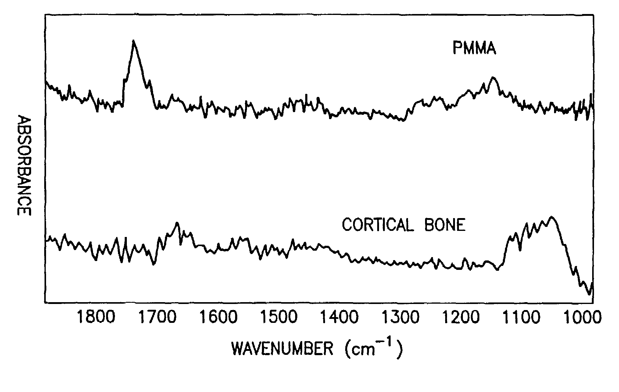
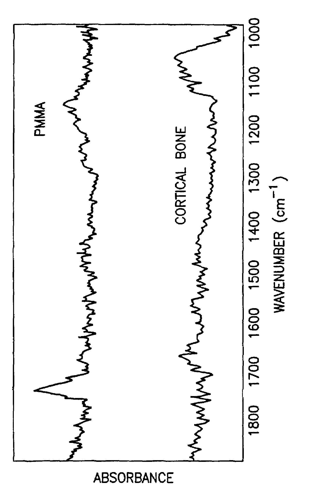
When revision surgery is necessary to replace the old hip stem with a new one, it is extremely difficult for the surgeon to visually discern the PMMA from the bone in the femoral canal, and thus to adequately remove it.
Although metal fillings can easily be discerned from teeth, it is sometimes difficult to discern non-amalgam-based fillings made of composite materials (Krejci I., Schupbach P., Balmelli F., Lutz F., (1999), “The Ultrastructure of a Compomer Adhesive Interface in Enamel and Dentin, and its Marginal Adaptation Under Dentinal Fluid as Compared to that of a Composite”, Dent. Mater., 15:349–358; Lutz F., Krejci I., (2000), “Amalgam Substitutes: A Critical Analysis”, J. Esthet. Dent., 12:146–159; Tate W. H., You C., Powers J. M., (2000), “Bond Strength of Compomers to Human Enamel”, Oper. Dent., 25:283–291; Attin T., Opatowski A., Meyer C., Zingg-Meyer B., Monting J. S., (2000), “Class II Restorations With a Polyacid-Modified Composite Resin in Primary Molars Placed in a Dental Practice: Results of a Two-Year Clinical Evaluation”, Oper. Dent., 25:259–264) or PMMA cement, from the tooth itself.
To date, mid-infrared fiber optic spectroscopic app

Method used


Image

  • Utilization of an infrared probe to discriminate between materials
  • Utilization of an infrared probe to discriminate between materials

Examples


Embodiment Construction

[0051]The present invention involves providing an IFOP which is operative in the mid-infrared region of the EM (approximately 400 cm−1 to 5,000 cm−1) or in the near infrared region of the EM (approximately 5,000 cm−1 to 14,000 cm−1).

[0052]The probe for use in the present invention can detect infrared radiation by ATR or by reflection. In either case, the evaluation of the region of interest to determine whether it is a host tissue or a non-host material can be carried out by, for example, peak shift analysis, peak area analysis, a combination of peak shift analysis and peak area analysis or by chemometric parameters.

[0053]An example of a probe for use in the present invention comprises an ATR element, or can receive reflected IR energy directly, and has an input end and an output end for receiving IR and transmitting attenuated IR radiation, respectively (see U.S. Pat. Nos. 5,170,056 and 5,923,808, the entire contents of both U.S. Pat. Nos. 5,170,056 and 5,923,808 are incorporated b...


PUM


Abstract

A method of evaluating the surface of a material that has a distinguishable infrared spectrum comprising (a) positioning an infrared fiber optic probe to be in contact with a surface of the sample or material at a region of interest for detecting attenuated total reflectance or within a sufficient distance from the surface of the region for detecting reflection, (b) detecting mid- or near-infrared radiation attenuated total reflectance or reflection off of the surface of the sample or the material, (c) analyzing the infrared radiation from step (b) for at least one of peak height, peak area, frequency and chemometric parameters, and (d) actuating the removal device when a signal from the infrared fiber optic probe is between pre-selected values for at least one of peak height, peak area, frequency and chemometric parameters for the sample of the material.

Description

CROSS REFERENCE TO RELATED APPLICATION[0001]The present application claims the benefit of Provisional Application Ser. No. 60 / 289,984, filed May 10, 2001, for which priority under 35 USC 119(e) is claimed.BACKGROUND OF THE INVENTION[0002]1. Field of the Invention[0003]The present invention concerns the application of a probe operative in the mid- or near-infrared (“IR”) region of the electromagnetic spectrum (“EM”) for in situ sensing of the absorption of infrared energy or reflected infrared energy of a material that has a distinguishable infrared spectrum and removing such material with a combined ablator, cutter, carver or polisher.[0004]More specifically, the present invention concerns the application of a probe operative in the mid- or near-IR region of the EM for in situ sensing of the absorption of infrared energy or reflected infrared energy for distinguishing between two materials that have different infrared spectra and separating or removing one material from the other wi...

Claims


Application Information

Patent Timeline
IPC IPC(8): A61B6/00A61B5/00G01N21/35G01N21/55
CPCA61B5/0059G01N21/552A61B5/4504G01N21/359G01N2201/0846G01N21/35G01N2021/559
Inventor CAMACHO, NANCY P.BOSTROM, MATHIAS P. G.BERTHA, STEVE L.
Owner HOSPITAL FOR SPECIAL SURGERY
Why Eureka
Try Eureka