
Fuel cell

a fuel cell and single chamber technology, applied in the field of single chamber fuel cells, can solve the problems of power generation efficiency liable to drop

Active Publication Date: 2007-01-30
SHINKO ELECTRIC IND CO LTD
View PDF7 Cites 105 Cited by
  • Summary
  • Abstract
  • Description
  • Claims
  • Application Information

AI Technical Summary

Benefits of technology

[0009]An object of the present invention is to provide a single chamber fuel cell where a cell is placed in a mixed fuel gas of a fuel gas and oxygen mixed together wherein even if ionization of oxygen and the reaction between the oxygen ions and fuel gas proceed simultaneously at the same surface of the cell, electricity can be taken out and the loss due to conduction of the oxygen ions produced can be kept to a minimum.
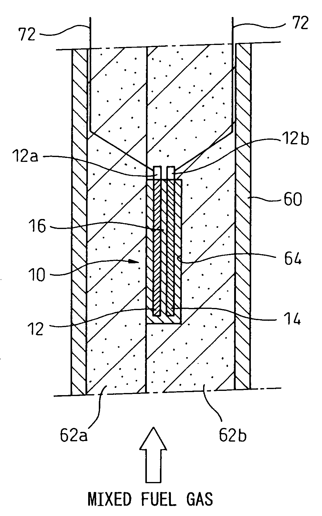
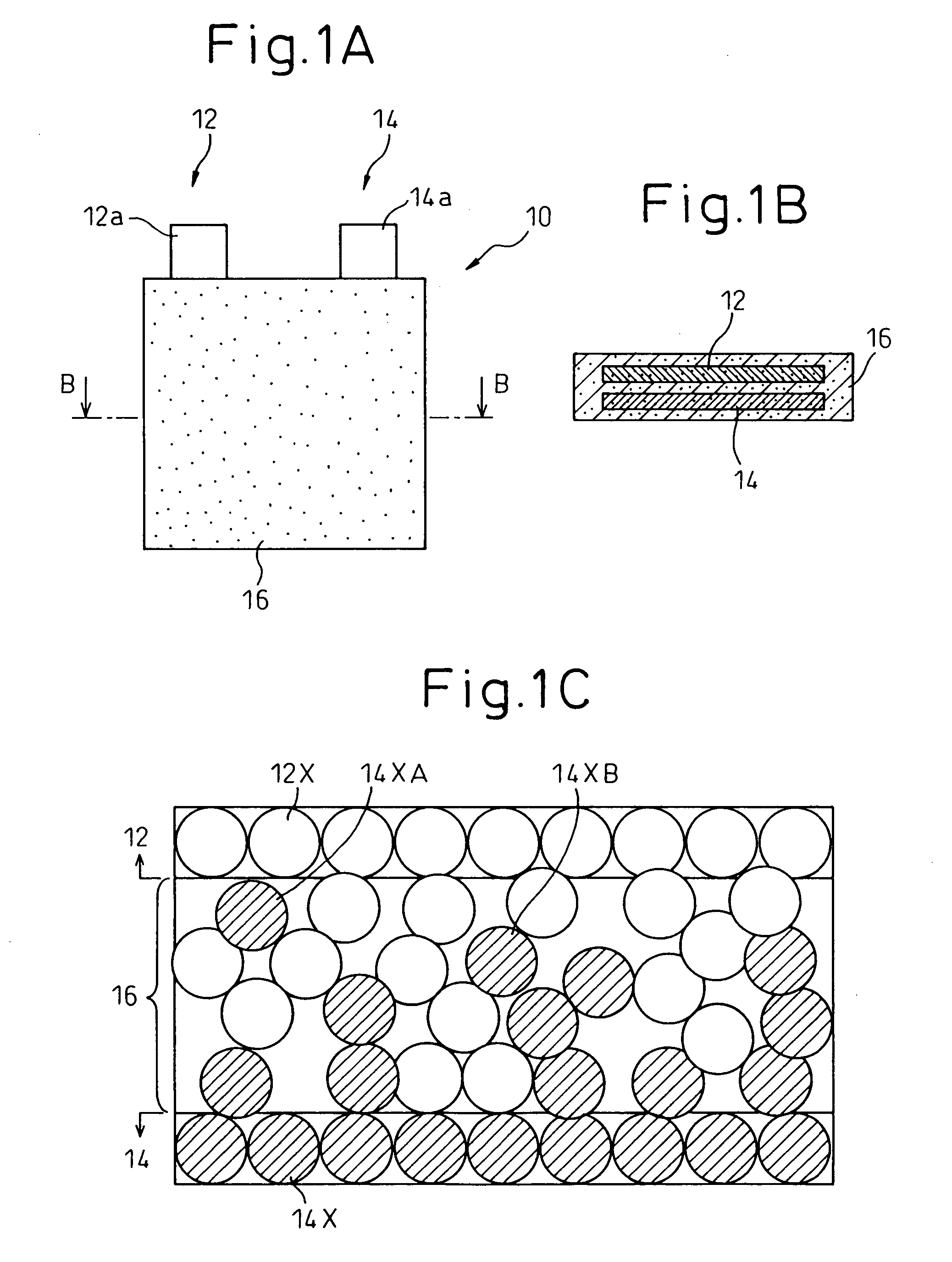
[0012]In the present invention, preferably the p-type semiconductor and n-type semiconductor are provided between them with a porous pn mixed layer formed by particles of the p-type semiconductor and particles of the n-type semiconductor mixed together to an extent enabling mixed fuel gas to pass, whereby the pn junction area of the p-type semiconductor and n-type semiconductor can be enlarged. Further, by mixing an oxidation catalyst into the pn mixed layer, the reaction between the fuel gas and oxygen at the pn junction can be accelerated.

Problems solved by technology

Therefore, in a single chamber fuel cell, the power generation efficiency is liable to drop.
From this viewpoint as well, in a single chamber fuel cell, the power generation efficiency is liable to drop.

Method used


Image

  • Fuel cell
  • Fuel cell
  • Fuel cell

Examples


example 1

[0047](1) Production of pn Junction Type Semiconductor 10

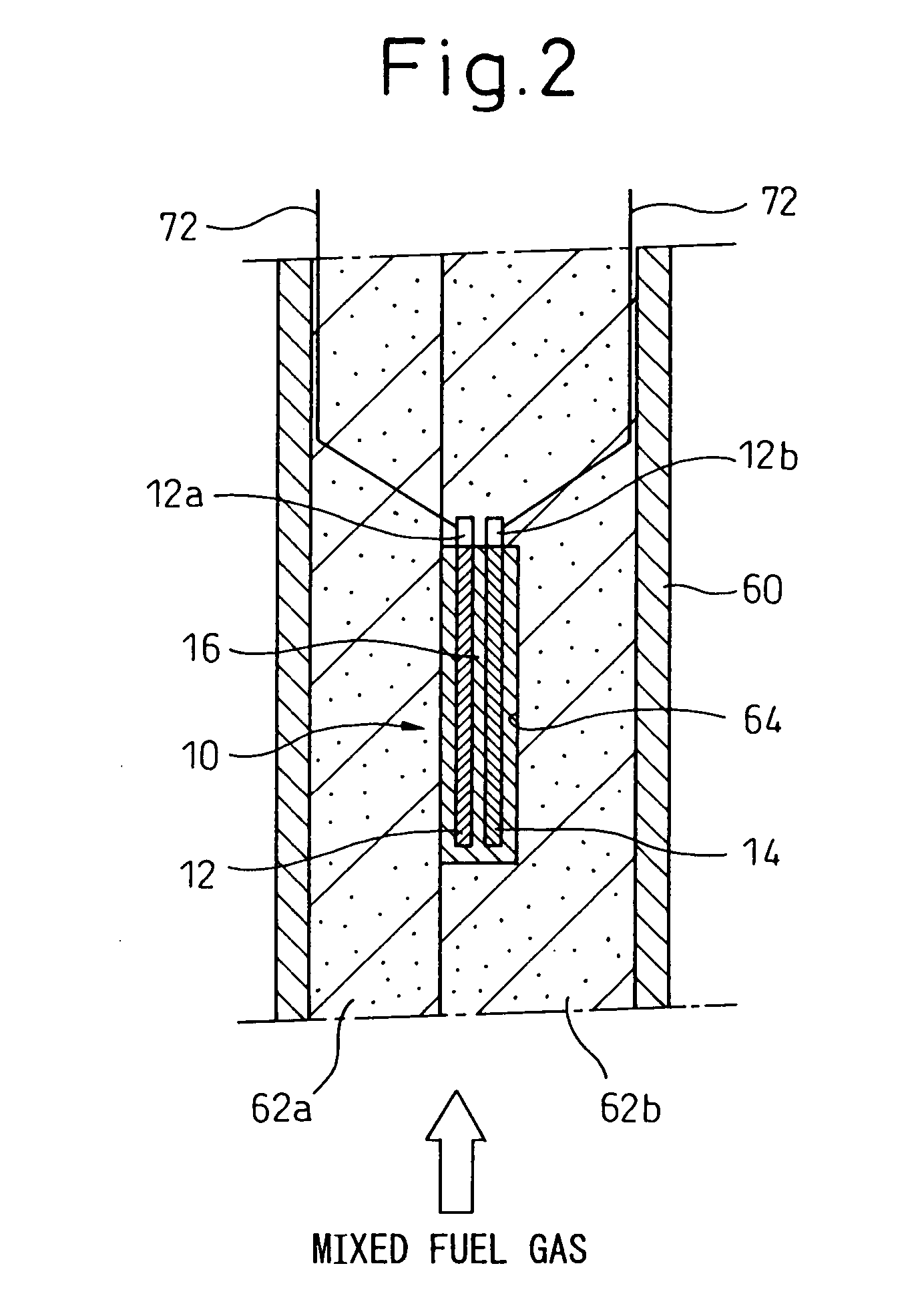
[0048]A Pt mesh welded to one end of the Pt wire 72 was dipped in a 0.5 mol / L aqueous solution of cobalt acetate, then was heated by an industrial drier to break down the cobalt acetate to cobalt oxide (CoO). The work was repeated tens of times to form a p-type semiconductor precursor. Further, a Pt mesh welded to one end of the Pt wire 72 was coated with a paste comprised of a powder of zinc oxide (ZnO) to which terpineol was added and dried at 100° C. to form an n-type semiconductor precursor.

[0049]Further, equimolar amounts of cobalt acetate and zinc oxide were mixed, then nickel oxide (5 wt %) was mixed to obtain a mixed power. Terpineol was added to this to obtain a pn mixed layer paste. Next, the obtained p-type semiconductor precursor and n-type semiconductor precursor were bonded through a pn mixed layer paste to obtain a bonded assembly. The outer circumference of this bonded assembly was also coated with the pn mixed...

example 2

[0056]The pn junction type semiconductor 10 used in Example 1 was placed on a hot plate and ethanol was dropped on the pn junction type semiconductor 10. The power generation potential and short-circuit current were measured by a multimeter. Further, the temperature of the hot plate was also changed and the power generation potential and short-circuit current of the resultant pn junction type semiconductor 10 were measured. The results are shown together in Table 1.

[0057]

TABLETemperaturePower generationShort-circuit(° C.)potential (mV)current (μA)Room610.2temperature501562.960118—7080—

[0058]As clear from Table 1, the pn junction type semiconductor 10 exhibited a power generation function even at room temperature. This phenomenon is believed to be derived from the fact that ethanol exhibits a predetermined vapor pressure even under room temperature, so the ethanol vapor reacts with the oxygen in the air. This is judged to be because the maximum power generation potential is exhibited...

example 3

[0059]The same procedure was followed as in Example 2 to measure the power generation potential except for maintaining the temperature of the hot plate at 50° C. and using methanol instead of ethanol. As a result, the power generation potential of the pn junction type semiconductor 10 was 41 mV. Even with methanol, it is possible to generate power by the pn junction type semiconductor 10.


PUM


Abstract

A single chamber fuel cell comprised of a cell arranged in a mixed fuel gas comprised of hydrogen or another fuel gas and oxygen, wherein the cell used is a pn junction type semiconductor having electrodes of a p-type semiconductor with carriers of holes and an n-type semiconductor with carriers of electrons connected to ends of electrical takeout wires, and each of the p-type semiconductor and n-type semiconductor is formed porous to an extent enabling the mixed fuel gas to pass.

Description

BACKGROUND OF THE INVENTION[0001]1. Field of the Invention[0002]The present invention relates to a fuel cell, more particularly relates to a single chamber fuel cell in which a cell is placed in a mixed fuel gas comprised of hydrogen or another fuel gas and oxygen.[0003]2. Description of the Related Art[0004]Science, vol. 288 (2000), p. 2031–2033, Journal of The Electrochemical Society, 149 (2) A133–A136 (2002), etc. propose a single chamber fuel cell shown in FIG. 5. The single chamber fuel cell shown in FIG. 5 consists of a cell 106, comprised of a solid electrolyte layer 100 on the two sides of which a cathode layer 102 and anode layer 104 are formed, placed in a chamber 110 supplied with a mixed fuel gas of a fuel gas and oxygen or an oxygen-containing gas through a feed pipe 108. The drive temperature of the fuel cell is about 500 to 600° C. The gas in the chamber 110 is exhausted outside of the system through an exhaust pipe 112.[0005]According to the single chamber fuel cell ...

Claims


Application Information

Patent Timeline
IPC IPC(8): H01M8/02H01M4/90H01M4/86H01M8/00H01M8/04H01M8/10H01M8/12
CPCH01M4/8605H01M4/90H01M8/10H01M8/04089Y02E60/521Y02E60/50
Inventor SUGANUMA, SHIGEAKIHORIUCHI, MICHIOWATANABE, MISAFUKASAWA, RYO
Owner SHINKO ELECTRIC IND CO LTD
Learn More