Diffraction-based diagnostic devices

a diagnostic device and diffraction technology, applied in the field of detecting analytes in a medium, can solve the problems of complex visualization device, high cost of prior systems and devices, and inability to view the diffraction pattern without training

Inactive Publication Date: 2007-01-30
KIMBERLY-CLARK WORLDWIDE INC
View PDF210 Cites 30 Cited by
  • Summary
  • Abstract
  • Description
  • Claims
  • Application Information

AI Technical Summary

Benefits of technology

[0017]By “diffraction” it is meant the phenomenon, observed when waves are obstructed by obstacles, of the disturbance spreading beyond the limits of the geometrical shadow of the object. The effect is marked when the size of the object is of similar order as the wavelength of the waves. In the present invention, the obstacles are analytes (with or without or attached microparticles) and the waves are light waves.
[0018]The present invention provides a low-cost, disposable biosensor which can be mass produced. The biosensors of the present invention can be produced as a single test for detecting an analyte or it can be formatted as a multiple test device. The uses for the biosensors of the present invention include, but are not limited to, detection of chemical or biological contamination in garments, such as diapers, the detection of contamination by microorganisms in prepacked foods such as fruit juices or other beverages, and the use of the biosensors of the present invention in health diagnostic applications such as diagnostic kits for the detection of antigens, microorganisms, and blood constituents. It should be appreciated that the present invention is not limited to any particular use or application.

Problems solved by technology

Many of the prior systems and devices are, however, relatively expensive and require a trained technician to perform the test.
A drawback to this type of device is, however, the fact that the diffraction pattern is not discernible by the naked eye and, thus, a complex visualization device is needed to view the diffraction pattern.
Also, the device is generally not able to detect smaller analytes that do not produce a noticeable diffraction pattern.
Drawbacks of this device are the relatively high cost of the device, problems associated with controlling the various layers that are placed on the surface, and the high variability of human color perception and discrimination.

Method used


Image

  • Diffraction-based diagnostic devices
  • Diffraction-based diagnostic devices

Examples


Embodiment Construction

[0021]The invention will now be described in detail with reference to particular embodiments thereof. The embodiments are provided by way of explanation of the invention, and not meant as a limitation of the invention. For example, features described or illustrated as part of one embodiment may be used with another embodiment to yield still a further embodiment. It is intended that the present invention include these and other modifications and variations as come within the scope and spirit of the invention.

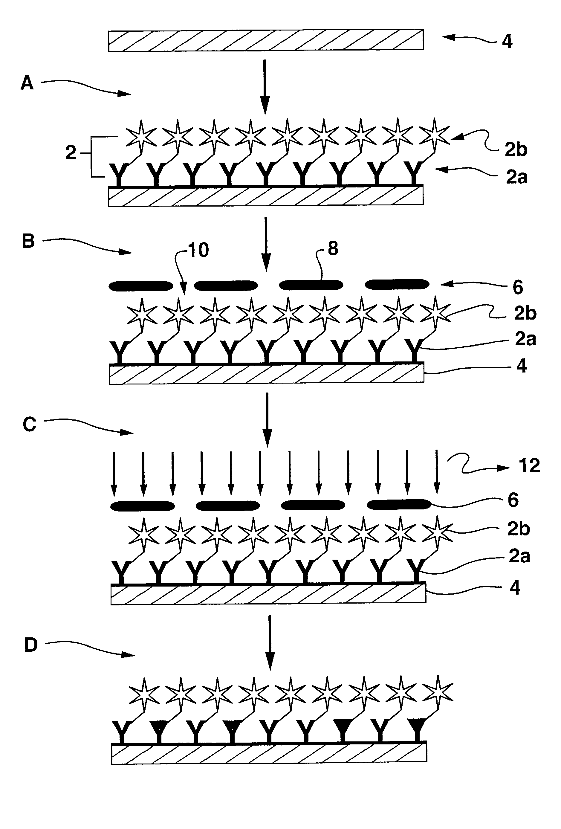
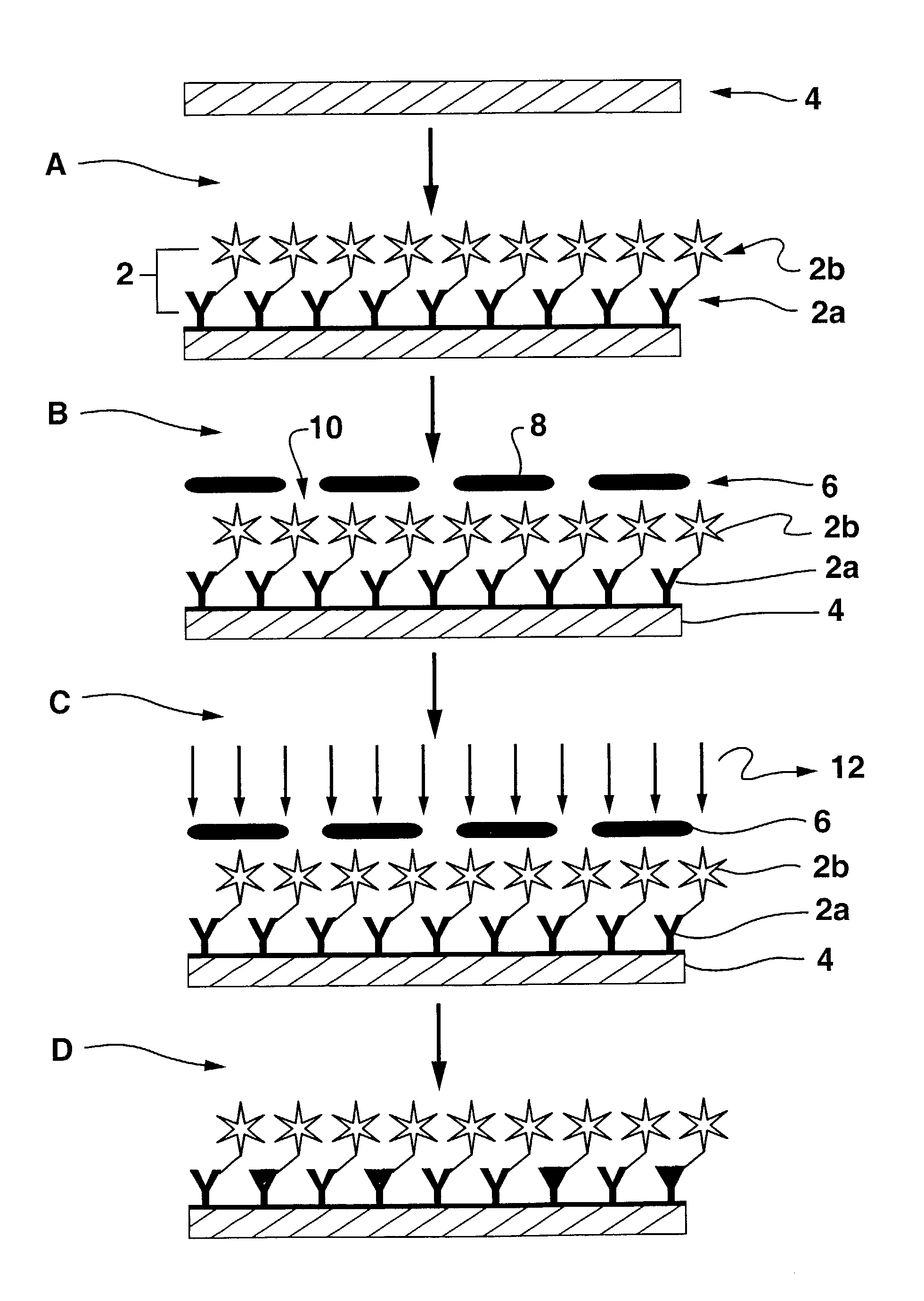
[0022]The present invention features improved biosensing devices, and methods for using such biosensing devices, for detecting and quantifying the presence or amount of an analyte of interest within a medium. The analytes that can be detected by the present invention include, but are not limited to, microorganisms such as bacteria, yeasts, fungi and viruses. The biosensing devices according to the invention are relatively inexpensive and have advantages over conventional micro-co...


PUM

PropertyMeasurementUnit
thicknessaaaaaaaaaa
thicknessaaaaaaaaaa
wavelengthaaaaaaaaaa

Abstract

A biosensor includes a substrate with a receptive material layer of radiation-absorbing member (RAM)-tagged biomolecules disposed thereon. The receptive material is specific for an analyte of interest. A pattern of active and deactivated areas of the receptive material are defined in the receptive material layer by a masking process wherein areas are exposed through a mask with a light source to induce deactivation.

Description

TECHNICAL FIELD OF THE INVENTION[0001]The present invention relates generally to the field of detecting analytes in a medium, and more particularly to a process for preparing analyte-specific diffraction based diagnostic sensors to indicate the presence of the analyte in a medium.BACKGROUND[0002]There are many systems and devices available for detecting a wide variety of analytes in various media. Many of the prior systems and devices are, however, relatively expensive and require a trained technician to perform the test. A need has been recognized in the art for biosensor systems that are easy and inexpensive to manufacture, and capable of reliable and sensitive detection of analytes. Reference is made, for example, to U.S. Pat. Nos. 5,922,550; 6,060,256; and 6,221,579 B1.[0003]U.S. Pat. No. 5,512,131 to Kumar, et al., describes a device that includes a polymer substrate having a metal coating. An analyte specific receptor layer is stamped onto the coated substrate. A diffraction p...

Claims


Application Information

Patent Timeline
Patent Type & Authority Patents(United States)
IPC IPC(8): C12Q1/00G01N21/47G01N33/543
CPCG01N21/4788G01N33/54373G03H1/182Y10S436/805Y10S436/815Y10S436/82Y10S436/901
Inventor SAYRE, CURTISKAYLOR, ROSANNCOHEN, DAVID
Owner KIMBERLY-CLARK WORLDWIDE INC
Why Eureka
Try Eureka