Method and apparatus for fabricating fiber Bragg gratings

a technology of fiber bragg grating and fiber bragg grating, which is applied in the direction of cladded optical fiber, multiplex communication, instruments, etc., can solve the problem of difficult design of the process for forming the desired refractive index modulation structure, inability to maintain the linearity between the pzt input voltage and the travel amount, and inability to produce a wide variety of products in small-lot production. a wide range of effects

Inactive Publication Date: 2007-01-30
OKI ELECTRIC IND CO LTD
View PDF7 Cites 53 Cited by
  • Summary
  • Abstract
  • Description
  • Claims
  • Application Information

AI Technical Summary

Benefits of technology

[0009]It is an object of the present invention to provide a method and apparatus for fabricating such fiber Bragg diffraction gratings that variation in refractive index modulation amplitude resulting from a transverse displacement of the optical fiber is reduced and that Bragg gratings having a phase shift portion in a desired position of the core of the optical fiber or having refractive index modulation amplitude changed as desired can be formed.
[0012]Unlike the conventional technique, which slightly moves or vibrates the optical fiber, the method or apparatus for fabricating fiber Bragg gratings according to the present invention slightly moves or vibrates the phase mask in the longitudinal direction, in order to create a phase shift portion or in order to change the refractive index modulation amplitude, so that the position of the core of the optical fiber will not move in the transverse direction of the optical fiber with reference to ultraviolet laser light. Therefore, the method or apparatus for fabricating fiber Bragg gratings according to the present invention enables Bragg diffraction gratings to be formed in the core of the optical fiber with reduced variation in refractive index modulation amplitude.

Problems solved by technology

This method is suitable for mass production of limited types of products and is not suitable for small-lot production of a wide variety of products, because an expensive phase mask must be prepared for each code type.
In the example described in the non-patent document 3, the PZT receives quasi-square-wave linear variations in voltage, and the linearity between the PZT input voltage and the travel amount cannot be maintained due to the hysteresis and creep characteristics.
Therefore, it is difficult to design the process for forming desired refractive index modulation structure in the core 110a of the optical fiber.

Method used


Image

  • Method and apparatus for fabricating fiber Bragg gratings
  • Method and apparatus for fabricating fiber Bragg gratings
  • Method and apparatus for fabricating fiber Bragg gratings

Examples


first embodiment

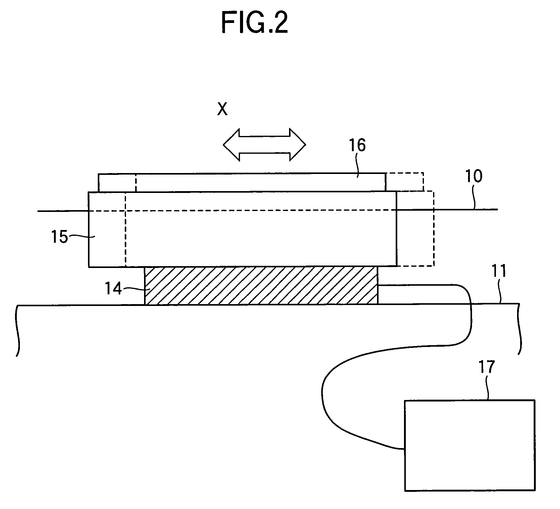
[0034]FIG. 2 is a diagram illustrating operation of a slight-movement stage 14 of an apparatus for fabricating FBGs according to the first embodiment of the present invention. The operation of the slight-movement stage 14 is controlled by adjusting the voltage applied to a piezoelectric element of the slight-movement stage 14 by means of a drive circuit (a direct-current (DC) voltage generator 17 in FIG. 2) in accordance with a control signal from a control unit (not shown) such as a personal computer. The control unit of the stage system 12 and the control circuit of the slight-movement stage 14 are generally a single personal computer.

[0035]FIGS. 3A and 3B are diagrams illustrating a method for fabricating FBGs according to the first embodiment (operation of the apparatus for fabricating FBGs according to the first embodiment). FIG. 3A illustrates a step of forming refractive index modulation structure before a phase mask 16 is shifted, and FIG. 3B illustrates a step of forming re...

second embodiment

[0046]Instead of the DC voltage generator (denoted by a reference numeral 17 in FIG. 2) which is used to drive the slight-movement stage in the first embodiment, a function voltage generator is used in the second embodiment, in order to apply a voltage amplitude of a desired function waveform to a piezoelectric element of the slight-movement stage and vibrate a phase mask. In the second embodiment, the vibration of the phase mask by means of the slight-movement stage causes the amplitude of the refractive index modulation in the core of the optical fiber to change, resulting in apodization, for instance.

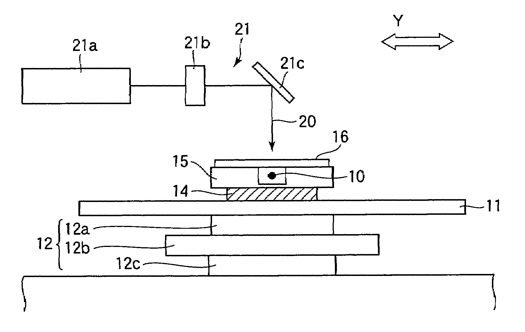
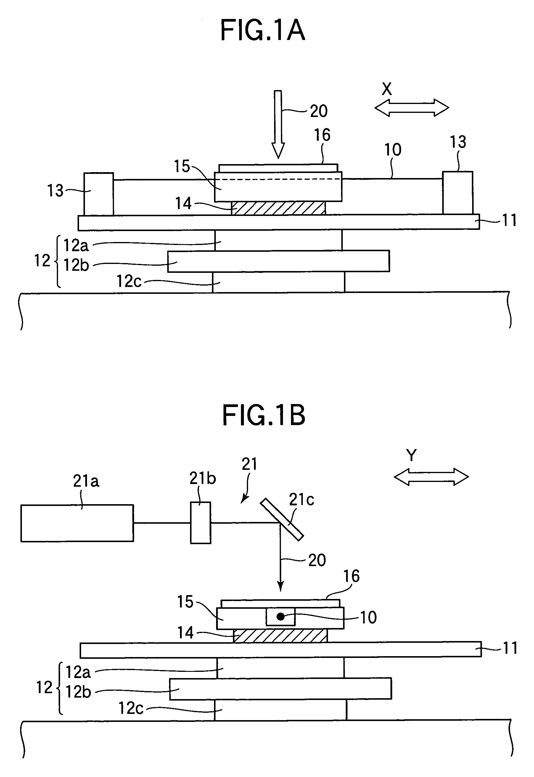
[0047]As shown in FIG. 1, a method for fabricating FBGs according to the second embodiment (operation of the fabrication apparatus according to the second embodiment) includes a step of forming periodic refractive index modulation structure in the core 10a of the optical fiber in the longitudinal direction of the optical fiber 10 by scanning the optical fiber 10 with the ultraviolet ...

third embodiment

[0055]A method for fabricating FBGs according to the third embodiment is provided to fabricate FBGs having both a phase shift portion and a change in the amplitude of refractive index modulation; In the method for fabricating FBGs according to the third embodiment, a signal formed by synthesizing the output of a DC voltage generator in the first embodiment and the output of a function voltage generator in the second embodiment is supplied to a piezoelectric element of a slight-movement stage, in order to vibrate or slightly move a phase mask 16.

[0056]The method for fabricating FBGs according to the third embodiment (operation of the apparatus for fabricating FBGs according to the second embodiment) includes a step of forming periodic refractive index modulation structure in the core 10a of the optical fiber, in the longitudinal direction of the optical fiber 10, by scanning the optical fiber 10 with the ultraviolet laser light 20 in the longitudinal direction (X-axis direction) in a...


PUM


Abstract

A method for fabricating fiber Bragg gratings including: scanning a photosensitive optical fiber with ultraviolet laser light in a longitudinal direction of the optical fiber by means of a phase mask method, thereby forming periodic refractive index modulation structure in a core of the optical fiber in the longitudinal direction; and instantaneously moving a phase mask used in the phase mask method by a predetermined distance in the longitudinal direction, thereby forming a phase shift portion in the periodic refractive index modulation structure formed in the core of the optical fiber, when a radiation position of the ultraviolet laser light reaches a predetermined position, in the middle of the scanning step using the ultraviolet laser light.

Description

BACKGROUND OF THE INVENTION[0001]1. Field of the Invention[0002]The present invention relates to a method and apparatus for fabricating fiber Bragg gratings (FBGs), particularly, a method and apparatus for fabricating FBGs having a phase shift portion or a change in refractive index modulation amplitude (apodization, for instance).[0003]2. Description of the Related Art[0004]A phase mask method is known as a method for fabricating FBGs by forming Bragg diffraction gratings in a core of an optical fiber. In the phase mask method, the interference light of the ultraviolet laser light is exposed to a core of an optical fiber, thereby forming a periodic refractive index modulation structure in the core of the optical fiber in the longitudinal direction of the optical fiber. See non-patent document 1, Toru Mizunami, “Optical Fiber Bragg Gratings”, OYO BUTURI, Vol. 67, No. 9 (1998), pp. 1029–1034.[0005]FBGs having a phase shift portion are used in optical code division multiplexing (OCDM)...

Claims


Application Information

Patent Timeline
Patent Type & Authority Patents(United States)
IPC IPC(8): G02B6/34G02B5/18G02B6/00G02B6/02G02B6/10H04J14/00
CPCG02B6/02152G02B6/02138G02B6/02
Inventor SASAKI, KENSUKENISHIKI, AKIHIKO
Owner OKI ELECTRIC IND CO LTD
Why Eureka
Try Eureka