

Reactive liquid based gas storage and delivery systems
- Summary
- Abstract
- Description
- Claims
- Application Information
AI Technical Summary
Benefits of technology
Problems solved by technology
Method used
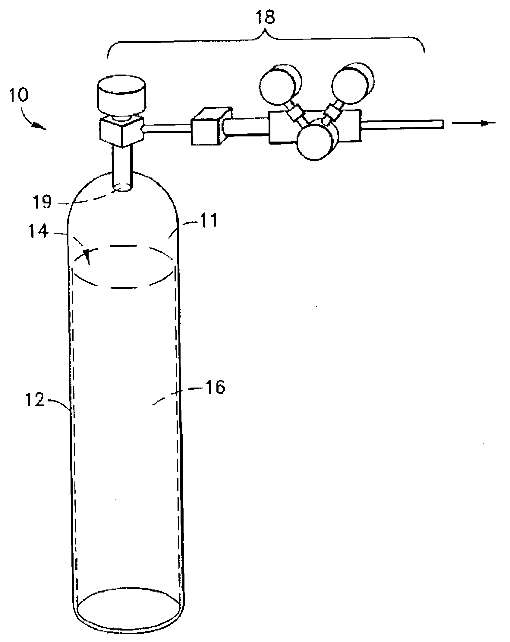
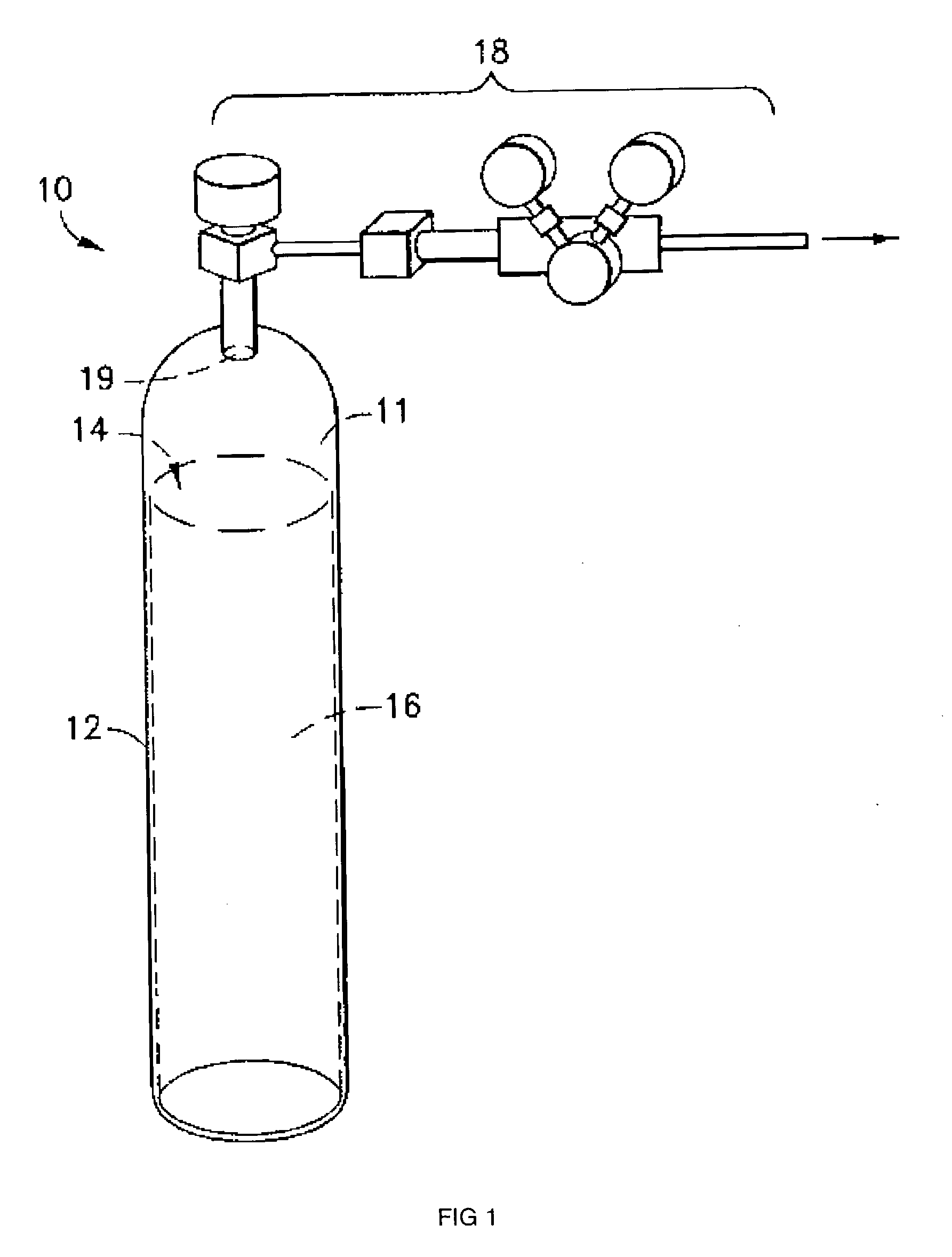
Image

Examples
example 1
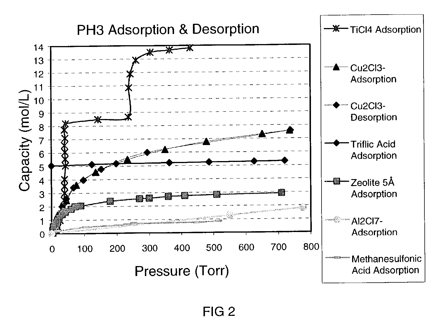
BMlM+Al2Cl7−, Lewis Acidic Ionic Liquid for PH3
[0077]Molecular modeling was used to calculate a binding energy, ΔErxn, for this Lewis acidic ionic liquid with PH3. The ionic liquid was modeled as an ion-pair, using 1,3-dimethylimidazolium as the cation, Al2Cl77− as the anion, and it was assumed that one equivalent of PH3 reacted per equivalent of Al2Cl7− anion (concentration of Al2Cl7−=3.2 mol / L). Structures were determined based on minimum energy geometry optimization using Density Functional Theory (DFT) at the BP level with a double numerical (DN**) basis set. This Lewis acidic ionic liquid was calculated to have a ΔErxn of 0.71 kcal / mol, which suggests that the reaction is slightly unfavorable, although within the general limitations of error. To clarify the results of modeling, the following reaction was run.
[0078]In a glove box, 9.07 g of AlCl3 (2 equivalents) was slowly added to 5.94 g (1 equivalent) of 1-butyl-3-methylimidazolium chloride (BMlM+Cl). (It is assumed the anion...
example 2
BMlM+CuCl2−, Lewis Acidic Ionic Liquid For PH3
[0082]In a glove box, 3.10 g of CuCl was slowly added to a flask charged with 5.46 g of BMlM+Cl− (1:1 stoichiometry). (It is assumed the anion CuCl2− is formed from the reaction stoichiometry 1 equivalent CuCl to 1 equivalent BMlM+Cl−). The mixture was stirred overnight and stored. A glass insert was charged with 7.71 g of the ionic liquid (density=1.4 g / mL) and placed into a 50 mL reactor, and the general procedure for measuring PH3 reaction was followed. The Lewis acidic ionic liquid reacted with 7.6 mmol of PH3 at room temperature and 674 Torr, corresponding to 1.4 mol PH3 / L of ionic liquid. Equilibrium data points were not obtained and % reversibility and working capacity were not determined. But, this reactive liquid is expected to have a high % reversibility and, thus, a sufficient working capacity for a storage and delivery system.
example 3
BMlM+Cu2Cl3−, Lewis Acidic Ionic Liquid For PH3
[0083]Molecular modeling was used to approximate the effectiveness of BMlM+Cu2Cl3− as a reactive liquid. The ionic liquid was modeled as an ion-pair, using 1,3-dimethylimidazolium as the cation, Cu2Cl3− as the anion, and it was assumed that one equivalent of PH3 reacted with each equivalent of copper (concentration of Cu reactive groups=9.7 mol / L). Structures were determined based on minimum energy geometry optimization using Density Functional Theory (DFT) at the BP level with a double numerical (DN**) basis set. This Lewis acidic ionic liquid was calculated to have an average ΔErxn of −5.5 kcal / mol for its reaction with PH3. The results indicate that this ionic liquid should bind PH3 more strongly than BMlM+Al2Cl7− of Example 1. Since ΔGrxn is smaller in magnitude than ΔErxn and the optimum ΔGrxn for the pressure range 20 to 760 Torr at room temperature is ca. −3 kcal / mol, the result suggests that the binding properties of BMlM+Cu2Cl...
PUM
| Property | Measurement | Unit |
|---|---|---|
| Temperature | aaaaa | aaaaa |
| Temperature | aaaaa | aaaaa |
| Temperature | aaaaa | aaaaa |
Abstract
Description
Claims
Application Information