
Shield structure design to improve the stability of an MR head

Inactive Publication Date: 2007-02-20
HEADWAY TECH INC
View PDF11 Cites 38 Cited by
  • Summary
  • Abstract
  • Description
  • Claims
  • Application Information

AI Technical Summary

Benefits of technology

[0010]A first object of this invention is to provide an MR read head capable of decoding information stored on magnetic media with high area density and narrow trackwidths.
[0011]A second object of this invention is to provide an MR read head with improved electrical, magnetic, mechanical and thermal stability.
[0012]A third object of the present invention is to provide an MR read head with improved noise characteristics of the readback signal.
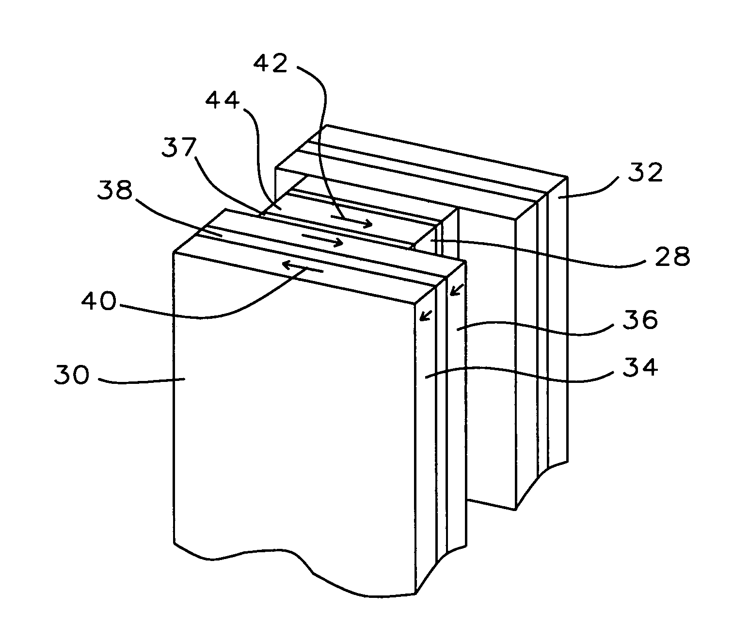
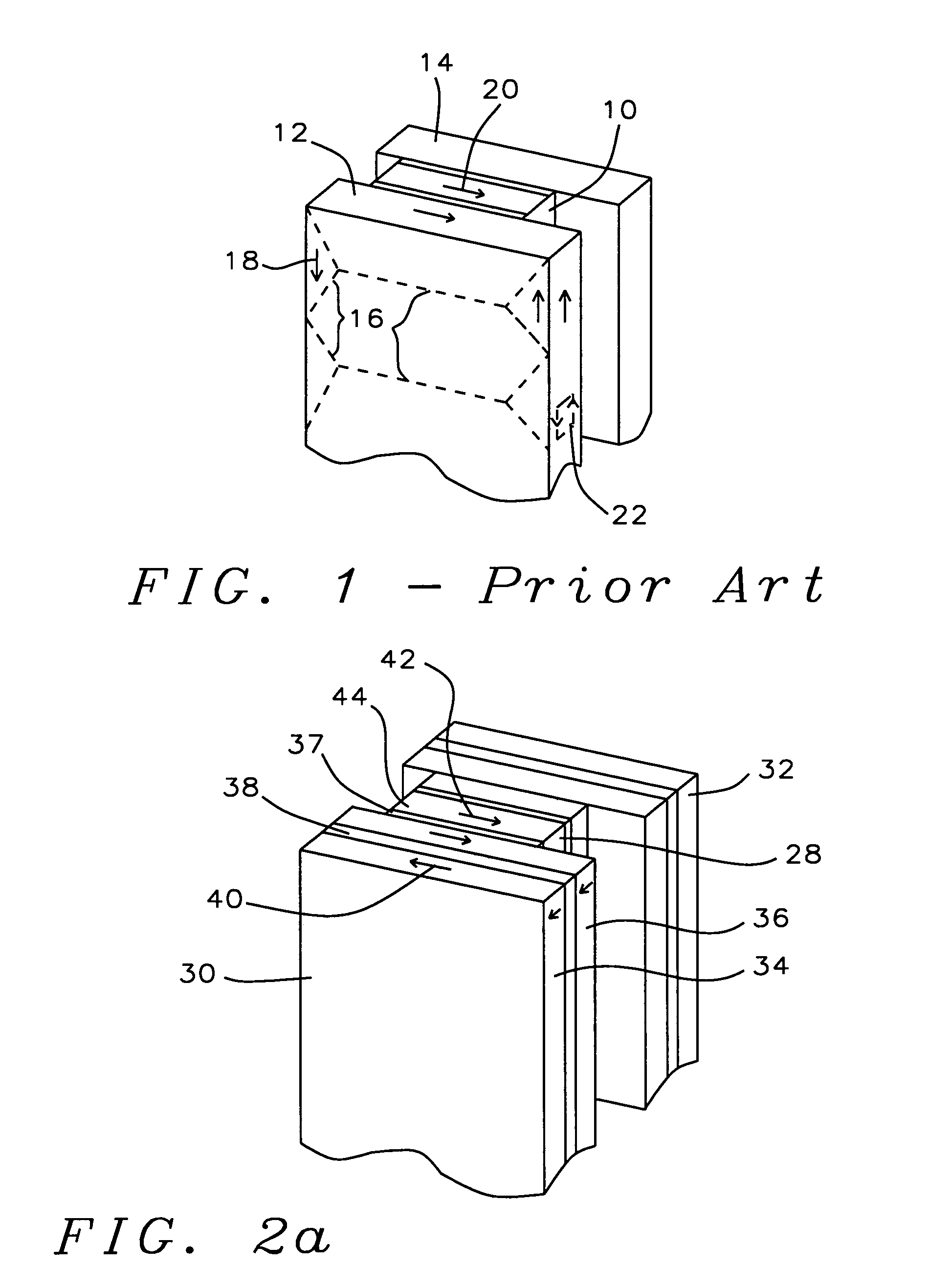
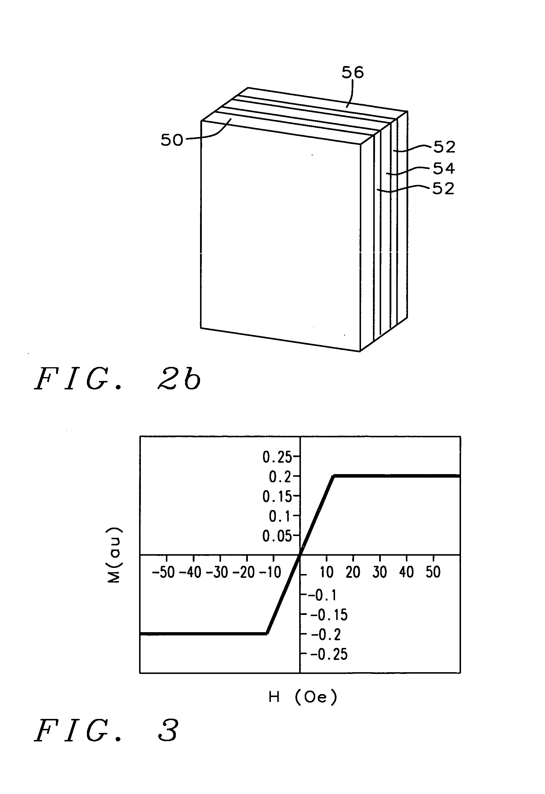
[0013]These objects will be achieved by providing a laminated magnetic shield for the MR sensor element, said shield having a stable domain structure that is substantially uniaxially anisotropic and closed at its edges. Said shield consists of two layers of ferromagnetic material in a mutually antiferromagnetic configuration separated by a layer of ruthenium (Ru) formed to a specific thickness so as to fix the antiferromagnetic configuration by quantum mechanical exchange coupling. The stability of the exchange-coupled system eliminates noise caused by variations in the domain structure while the domain closure loop naturally formed at the edges tends to reduce the occurrence of eddy currents. The uniaxial magnetic anisotropy of each ferromagnetic layers is maintained by the exchange coupling and causes its magnetization to rotate back to its easy axis direction after perturbation by external fields. This property helps to maintain the magnetic bias of the sensor element, increasing its stability and allowing it to continue to operate in the most linear portion of its response curve. Due to the coupling of the two layers, the rotation of their magnetization is coherent and their hysteresis is reduced under the action of external fields produced by the encoded media or the write portion of the read / write head assembly.

Problems solved by technology

This, in turn, increases the interaction between the magnetic properties of the shield and those of the sensor element, exacerbating whatever problems may exist in the shield design.
Unfortunately, the domain walls often split apart and merge as a result of stress variations.
In addition, the changing domain structure induces a noisy signal in the MR sensor, producing what is called Barkhausen noise in the sensor's readout signal.
A final, but by no means less significant disadvantage of the relatively isotropic arrangement of magnetizations of a typical shield, is that it makes it difficult to maintain the fixed bias of the magnetization of the MR sensor element itself.

Method used


Image

  • Shield structure design to improve the stability of an MR head
  • Shield structure design to improve the stability of an MR head
  • Shield structure design to improve the stability of an MR head

Examples


Embodiment Construction

[0019]The present invention provides a laminated magnetic shield structure whose design improves the stability and performance of an MR read head. Referring first to FIG. 1, there is shown a schematic drawing of a MR sensor element (10) and its surrounding magnetic shields (12) and (14) fabricated in accordance with the present art. The shields are typically formed of a single ferromagnetic layer and display a domain structure (16) that is substantially isotropic and subject to noise producing variations during the operation of the shield. The magnetizations of the various domains (18) are not aligned in the direction of the magnetic layer of the sensor element (20) and, therefore, do not assist in maintaining a consistent orientation of the sensor magnetization. The movement of the shield magnetic moments tend to cause eddy currents to form in the edges of the shield (22).

[0020]Referring now to FIG. 2a, there is shown a schematic drawing of an MR sensor element (28) and its surroun...


PUM


Abstract

A method for forming a laminated shield to improve the stability and performance of an MR read head and the MR read head formed using that shield. The shield consists of two layers of ferromagnetic material separated by a layer of ruthenium, allowing the ferromagnetic layers to form an antiferromagnetic configuration by means of a quantum mechanical exchange interaction. The antiferromagnetic configuration has a stable domain structure and a magnetization that forms closed loops around the shield edges thereby reducing noise in the readback signal and reducing disturbances to the magnetic state of the sensor element.

Description

BACKGROUND OF THE INVENTION[0001]1. Field of the Invention[0002]The present invention relates to the fabrication of an MR read head having a laminated magnetic shield structure for improved head stability and performance.[0003]2. Description of the Related Art[0004]A magneto-resistive (MR) read head consists of an MR sensor element that is positioned between two magnetic shields and electrically insulated from them by thin dielectric layers. The read head is typically a part of a combined read / write head assembly which also contains a magnetic inductive write head portion. The purpose of the magnetic shields is to exclude stray magnetic fields from the sensor element. Stray fields, in this context, include such fields as are produced by magnetically encoded data on portions of the magnetic medium not being accessed by the read / write head, as well as fields produced by the write head portion of the read / write assembly during its normal operation.[0005]The operation of magnetic shield...

Claims


Application Information

Patent Timeline
IPC IPC(8): G11B5/127G11B5/33
CPCG11B5/112G11B5/3912H01L43/08H10N50/10
Inventor LI, MINLIAO, SIMON H.HORNG, CHENG T.JU, KOCHAN
Owner HEADWAY TECH INC
Learn More