X-ray imaging system and imaging method

a technology of x-ray imaging and imaging method, applied in the field of x-ray imaging apparatus, can solve problems such as complex configuration of the apparatus, and achieve the effect of simple construction

Active Publication Date: 2007-02-20
MOMOSE ATSUSHI
View PDF2 Cites 135 Cited by
  • Summary
  • Abstract
  • Description
  • Claims
  • Application Information

AI Technical Summary

Benefits of technology

[0005]The present invention therefore sets out to resolve this situation. The object of the present invention is to provide an apparatus capable of X-ray imaging utilizing phase of X-rays with a simple construction.

Problems solved by technology

However, there are drawbacks with this technology in that the apparatus configuration is complex or a large-scale X-ray source such as a synchrotron radiation source is necessary.

Method used


Image

  • X-ray imaging system and imaging method
  • X-ray imaging system and imaging method
  • X-ray imaging system and imaging method

Examples


experimental example 1

[0058]Experimental example 1 shows the occurrence of the Talbot effect due to irradiation of a diffraction grating with X-rays.

[0059]Experimental Conditions

[0060]X-rays used: light of wavelength 0.1 nm emitted by a synchrotron.

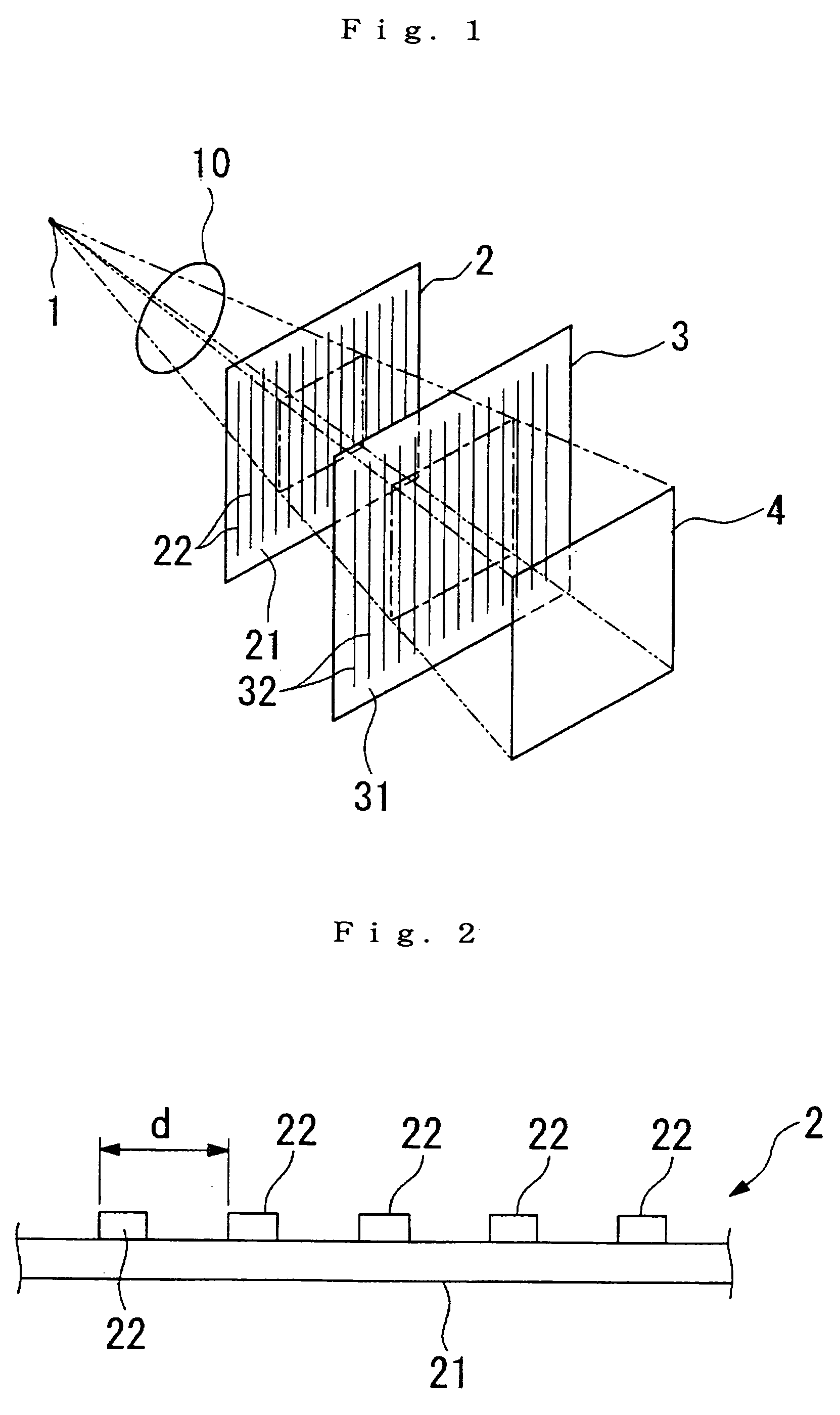
[0061]Diffraction grating: Gold pattern approximately 1 micron thick formed with a period d=8 microns on a 150 micron-thick glass plate.

[0062]The conditions for generating the Talbot effect using phase-type diffraction gratings are:

[0063]Z=(m+12)⁢⁢d2λ

[0064]Therefore, first, corresponding with when m=0, a self image of the diffraction grating should be formed when the distance Z from the first diffraction grating 2 to the detection surface is 32 cm. An X-ray image detector is then positioned at a position where the distance Z is 32 cm, and an image is recorded. The results is shown in FIG. 5. Similarly, when the distance Z is 64 cm, this situation is the most away from the above condition, and the self image is therefore unclear (FIG. 6). When the distance Z is...

experimental example 2

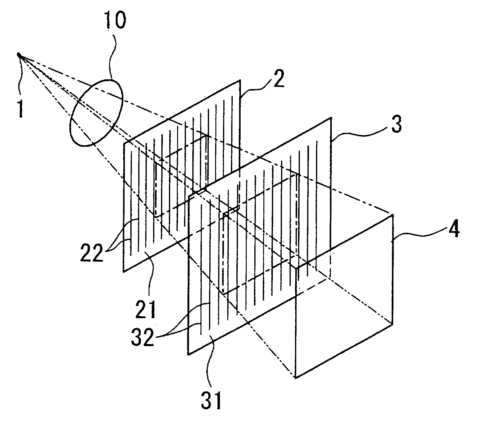
[0066]An experimental example 2 of the embodiment utilizing the X-ray Talbot effect is shown here.

[0067]Experimental Conditions

[0068]X-rays used: light of wavelength 0.1 nm emitted by a synchrotron.

[0069]Diffraction grating 2: Gold pattern approximately 1 micron thick formed with a period d=8 microns on a 150 micron-thick glass plate.

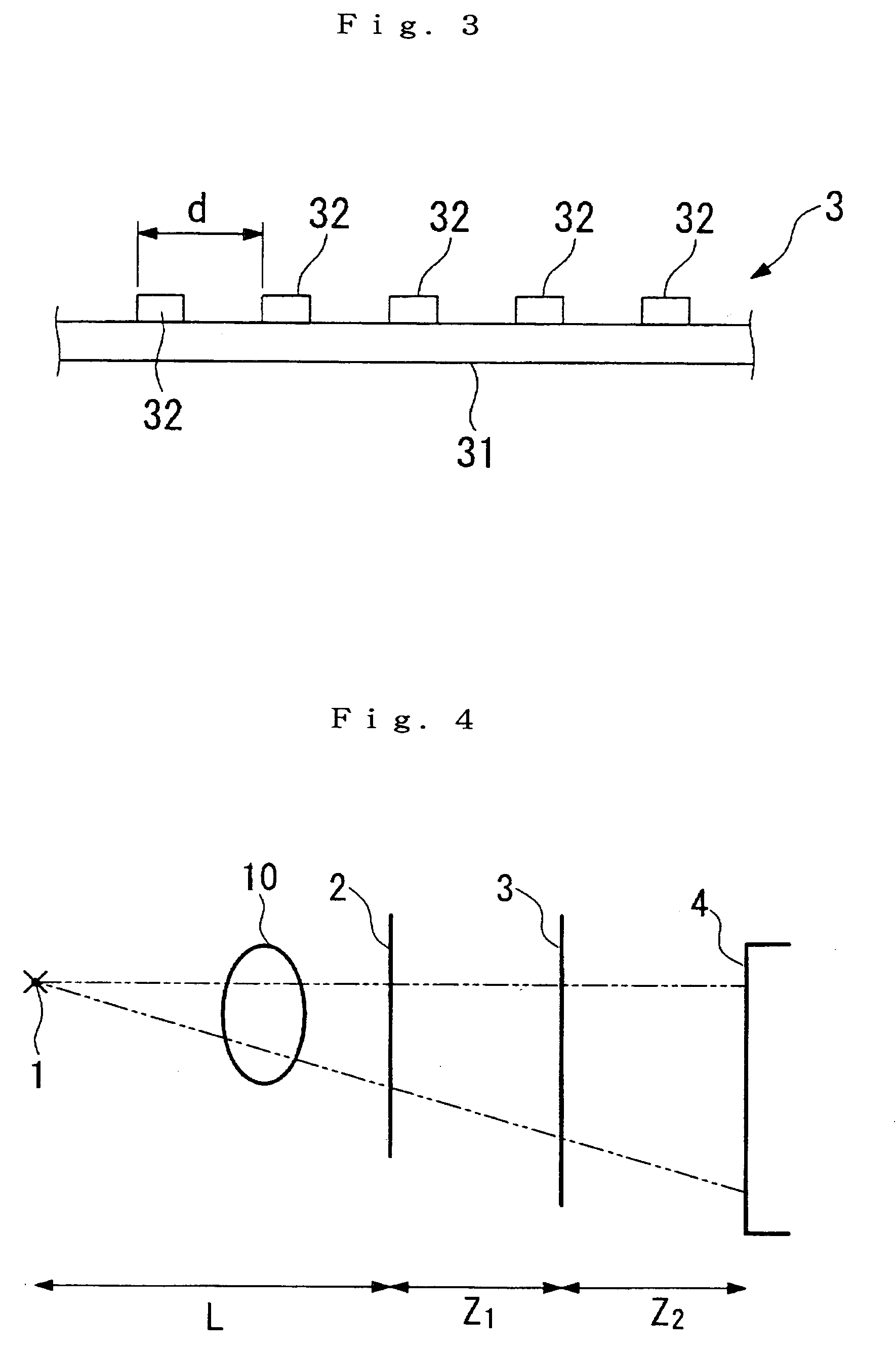
[0070]Diffraction grating 3: Gold pattern approximately 8 micron thick formed with a period d=8 microns on a 150 micron-thick glass plate.

[0071]Spacing Z1 of the diffraction gratings 2 and 3 is taken to be 32 cm for the Talbot effect to appear due to the diffraction grating 2. A plastic sphere approximately 1 mm in diameter is used as the test subject 10.

[0072]The test subject 10 is positioned between the X-ray source 1 and the first diffraction grating 2 just in front of the first diffraction grating 2.

[0073]X-rays emitted from the X-ray source are detected by the X-ray image detector arranged just behind the diffraction grating 3. As a result, it is p...

experimental example 3

[0079]Here, an experimental example of tomography is shown using the apparatus of this embodiment.

[0080]Experimental Conditions

[0081]The experimental conditions of experimental example 3 are the same as for experimental example 2.

[0082]The tomography employing this embodiment requires the following three procedures. Procedure 1 transforms X-ray images (hereinafter referred to as “moiré fringe images”) detected by the X-ray image detector 4 to “a distributed image of the X-ray deflection angle caused by refraction effects at the test subject 10” (hereafter referred to as a “phase shift differential image”). Procedure 2 acquires an image (hereinafter referred to as a “phase shift image”) mapping the shifts in phase by integrating the phase shift differential image. Procedure 3 reconstructs a three-dimensional image using tomography from phase shift images acquired in a plurality of photographing directions.

[0083]Procedure 1 employs a fringe scanning technique; that is one of diffracti...


PUM

PropertyMeasurementUnit
distanceaaaaaaaaaa
distanceaaaaaaaaaa
distanceaaaaaaaaaa

Abstract

The present invention provides an apparatus capable of X-ray imaging utilizing phase of X-rays. An X-ray imaging apparatus equipped with first and second diffraction gratings and an X-ray image detector are described. The first diffraction grating generates a Talbot effect and a second diffraction grating diffracts X-rays diffracted by the first diffraction grating. An image detector is provided to detect the X-rays diffracted by the second diffraction grating. In this manner, image contrasts caused by changes in phase of X-rays due to a subject arranged in front of the first diffraction grating or between the first diffraction grating and the second diffraction grating can be achieved.

Description

CROSS-REFERENCE TO RELATED APPLICATION[0001]This application is a continuation-in-part application of International Application No. PCT / JP03 / 16670, filed Dec. 25, 2003, incorporated herein by reference.FIELD OF THE INVENTION[0002]The present invention relates to an X-ray imaging apparatus utilizing phase of X-rays.RELATED ART[0003]In the visible light region, a Talbot interferometer where a Talbot effect is generated by a diffraction grating and a moiré fringe is generated by combining another diffraction grating is well-known. As a result, it is possible to visualize wavefronts of visible light, i.e. to generate image contrast utilizing phase.[0004]In the X-ray region, research and development of X-ray imaging apparatus employing phase, as disclosed, for example, in Japanese Patent Laid-open Publication H10-248833, is also well-known. However, there are drawbacks with this technology in that the apparatus configuration is complex or a large-scale X-ray source such as a synchrotron ...

Claims


Application Information

Patent Timeline
Patent Type & Authority Patents(United States)
IPC IPC(8): G01N23/04G01N23/20G21K1/06
CPCA61B6/06A61B6/483A61B6/484A61B6/4291G21K1/06G01N23/20075G21K2207/005A61B6/4092G01N23/041
Inventor MOMOSE, ATSUSHI
Owner MOMOSE ATSUSHI
Why Eureka
Try Eureka