
Multiple barrier filter apparatus

a filter apparatus and multi-barrier technology, applied in the direction of liquid transfer devices, feed/displacement of settling tanks, packaging, etc., can solve the problems of long life of the ro membrane, harmful when ingested by people, and the inability of the ro unit alone to consistently meet the relatively stringent requirements, etc., to improve the removal of microorganisms, unwanted ionic species, and organics

Inactive Publication Date: 2007-02-27
KINETICO
View PDF68 Cites 14 Cited by
  • Summary
  • Abstract
  • Description
  • Claims
  • Application Information

AI Technical Summary

Benefits of technology

[0006]By adding multiple barrier filter capabilities to a traditional under sink RO unit, improved removal of microbiological contaminants, unwanted ionic species, and organics can be achieved.
[0012]In a preferred embodiment, the filter apparatus includes a check valve in fluid communication with the second outlet port and downstream of the second filter element for preventing backflow of contaminated water into the filter apparatus. According to a feature of the invention, the check valve is a duck bill check valve installed in a treated water dispensing faucet in fluid communication with the second outlet port and through which treated water flows out of the filter apparatus. According to another feature the check is made of an antimicrobial material.
[0014]In an embodiment that facilitates under sink mounting, the bacterial filter element is disposed within the first sealed outer housing. According to a feature, at least one of the viral and bacterial filter membranes is generally cylindrical in shape and has a central void such that water flowing to and from the other of the viral and bacterial filter membrane flows within the central void. According to another feature, the first inlet port, first outlet port, second inlet port, and second outlet port are disposed on a single surface of the sealed outer housing.
[0017]In a preferred embodiment, the filter apparatus includes a check valve in fluid communication with the second outlet port and downstream of the second filter element for preventing backflow of contaminated water into the filter apparatus. According to a feature of the invention, the check valve is a duck bill check valve installed in a treated water dispensing faucet in fluid communication with the second outlet port and through which treated water flows out of the filter apparatus. According to another feature the check is made of an antimicrobial material.
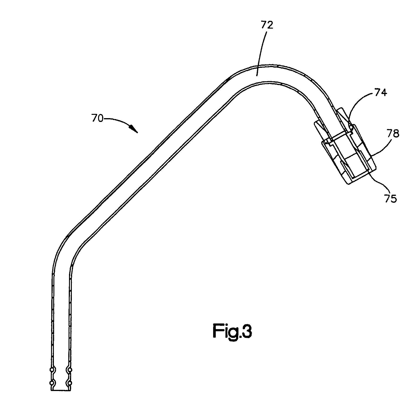
[0019]According to an embodiment of the invention, a treated water dispensing faucet for dispensing water that has been treated to remove contaminants includes a conduit for directing the flow of treated water from a filtration system to a dispensing station. The conduit has a first end connected to the filtration system and a second end that includes an orifice that opens to the dispensing station. A check valve is mounted to the second end for preventing the back flow of contaminants to the filtration system. According to a feature, the check valve is a duck bill check valve that includes antimicrobial material. According to yet another feature, a valve shield member substantially encloses the check valve for preventing contact between foreign objects and the check valve.

Problems solved by technology

This pre-treatment improves the operation and prolongs the life of the RO membrane.
There is increasing concern that some of the water supplies, both from wells, surface waters or even municipalities may, from time to time contain unwanted microbiological contaminants such as pathogens, that may be harmful when ingested by people, especially persons with immune system deficiencies.
While the pore size of the common RO membrane is sufficiently small to prevent the passing of microbiological contaminants, testing over the years has shown that the RO unit alone cannot consistently meet the relatively stringent requirements to be classified a “microbiological purifier” as defined in EPA in the “Guide Standard and Protocol for Testing Microbiological Water Purifiers” (1987 revision).
While there are several methods available to deal with such concerns, such as boiling the water for several minutes or adding anti-pathogen agents like iodine to the water, most of these are not convenient and / or may make the water less pleasant to drink.
These filters suffer from several practical drawbacks including the fact that they rely on electricity to function and also require relatively complex controls to ensure that water is not overheated due to extended exposure to the light.

Method used


Image

  • Multiple barrier filter apparatus
  • Multiple barrier filter apparatus
  • Multiple barrier filter apparatus

Examples


Embodiment Construction

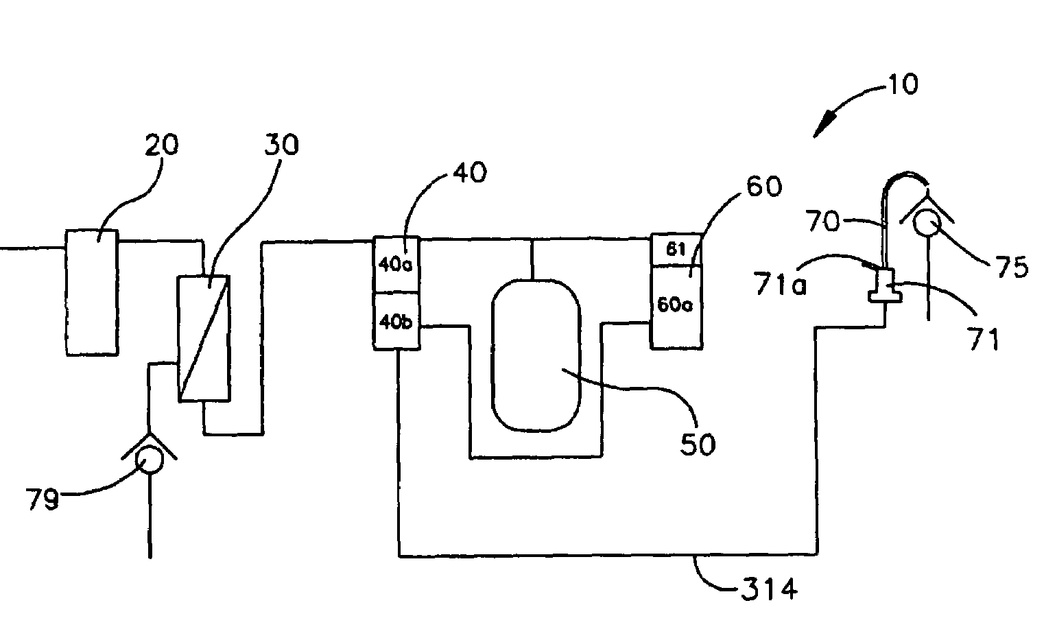
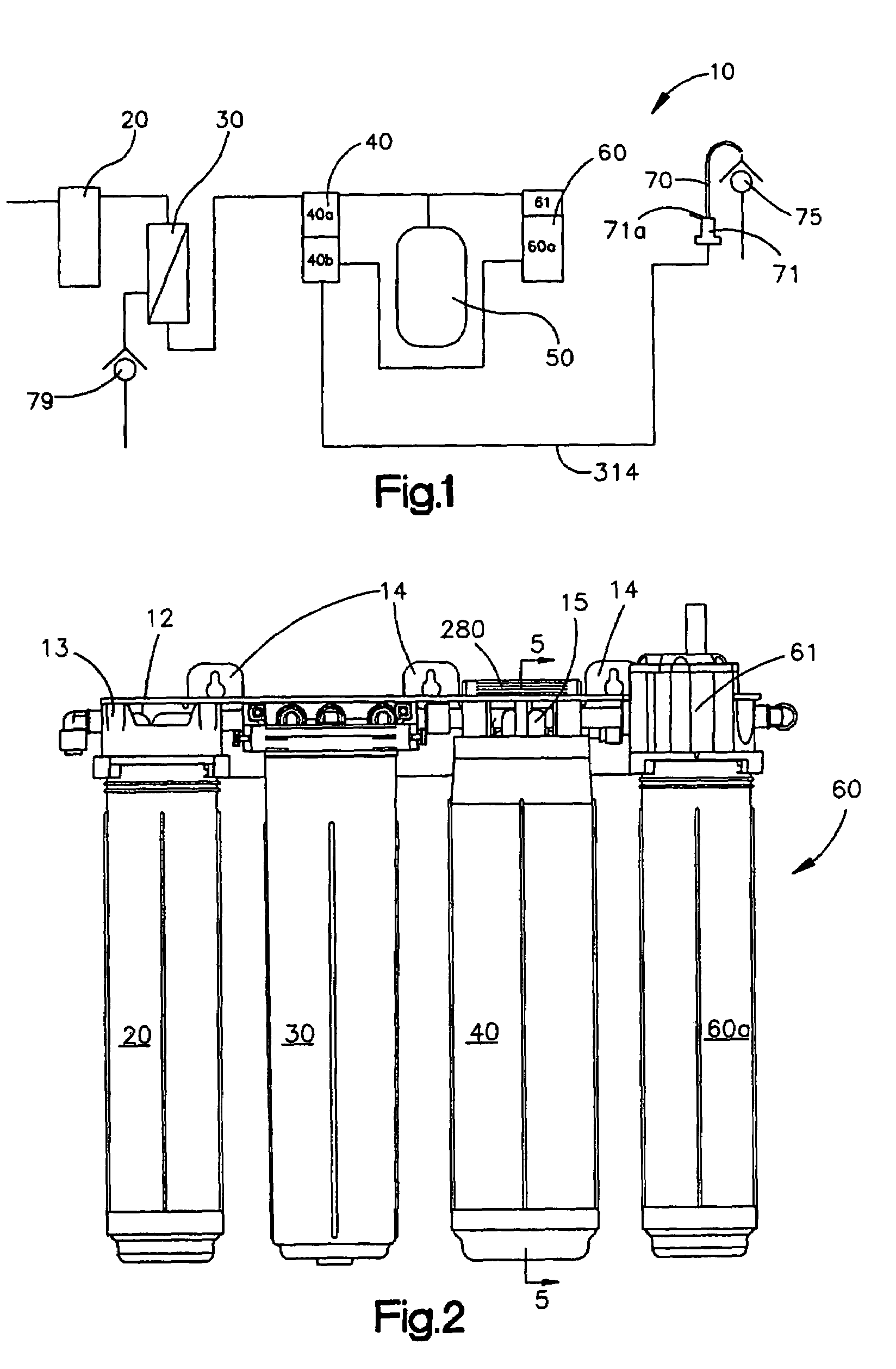
[0038]FIG. 1 illustrates schematically a water treatment system 10 for removing particulate and microbial contaminants from water. The water treatment system 10 designed for mounting under the sink in a typical residential kitchen and for dispensing treated water from a system dedicated faucet 70 including a flow control valve 71 having an operating handle 71a. The system includes a pre-filter 20 such as Kinetico part number 9309 and a reverse osmosis filter 30 (such as that disclosed in U.S. Pat. No. 4,650,586, assigned to assignee of the present invention and incorporated herein by reference) placed in series to remove a majority of contaminants typically found in residential water supplies. While an RO filter is described herein, it will be apparent to one of skill in the art that any cross flow membrane filter such as a nanofiltration unit, an ultrafiltration unit, or a microfiltration unit can be used to practice the present invention. The pre-filter 20 filters out entrained so...


PUM

PropertyMeasurementUnit
Lengthaaaaaaaaaa
Lengthaaaaaaaaaa
Flow rateaaaaaaaaaa

Abstract

A filter apparatus is provided which includes a first filter membrane element (40a), and a second bacterial filter membrane element. The first viral filter element (40a) is capable of treating water at a first second flow rate and is adapted to remove contaminants which are larger than a first size, while the second bacterial filter element (40b) is capable of treating water at a second higher flow rate and is adapted to remove contaminants which are larger than a second contaminant size. The first and second filter elements (40a), (40b) may be commonly housed within a sealed housing. An accumulating vessel (60) is placed in fluid communication with an outlet of the first filter element (40a) and an outlet of the second filter element (40b). The filter apparatus includes a duck bill type check valve (75) made of an antimicrobial material intermediate the second filter element (40b) and a dispensing faucet (70).

Description

TECHNICAL FIELD[0001]The present invention relates generally to filtering systems and in particular to a filtering apparatus that includes multiple filtering elements.BACKGROUND OF THE INVENTION[0002]For at least the last 15 years, there have been several configurations of “under-sink” reverse osmosis (RO) systems designed to improve the quality of a relatively small amount of water to be used for drinking and cooking by a homeowner. A few examples of such systems are described in U.S. Pat. Nos. 4,650,586 and 4,629,568 both of which are owned by the assignee of the present invention and incorporated herein by reference.[0003]An objective of typical under sink reverse osmosis systems is to decrease the total dissolved solids (TDS) of the supplied city or well water and thereby improve the taste, odor or chemical makeup of the water. These under the sink reverse osmosis systems can be upgraded to include additional unit processes to pre-treat the incoming water for chlorine or sedimen...

Claims


Application Information

Patent Timeline
IPC IPC(8): B01D35/153B01D35/30B01D36/02B01D36/04B01D35/143B01D61/08B01D61/10B01D61/18B01D61/20B01D61/58C02F1/44C02F1/50C02F9/00
CPCB01D35/301B01D61/08B01D61/10B01D61/18B01D61/20B01D61/58C02F9/005C02F2209/40B01D61/027B01D61/145B01D61/147B01D2201/4023C02F1/441C02F1/50B01D61/025Y10T137/87249Y10T137/9464Y10T137/9029Y10T137/9682C02F9/20B01D61/081
Inventor BROWN, KEITH E.PETERSON, PAULPARK, STUARTKINDEL, RONSKLAR, ERICMILLER, JOHNWEIGHT, KEN
Owner KINETICO
Learn More