Hinge for micro-mirror devices

a micro-mirror and hinge technology, applied in the direction of mountings, semiconductor devices, instruments, etc., can solve the problems of reducing the design complexity of the hinge, increasing the design complexity, and reducing the lifetime of the hinge memory, so as to facilitate the fabrication of optically flat mirrors, improve the elasticity, and simplify the manufacturing process

Active Publication Date: 2007-02-27
IGNITE INC
View PDF18 Cites 37 Cited by
  • Summary
  • Abstract
  • Description
  • Claims
  • Application Information

AI Technical Summary

Benefits of technology

[0015]Many of the advantages of the present invention are due to the material of which the hinge is composed. A doped semiconductor hinge offers a conductive means by which the micro-mirror can be biased while improving elasticity and simplifying the manufacturing process. In addition the material is robust under extreme temperatures and immune to the memory hinge effects caused by creep. Furthermore, the hinge architecture according to the present invention facilitates the fabrication of an optically flat mirror and further simplifies the manufacturing process by allowing a direct connection to the micro-mirror.

Problems solved by technology

The relaxation of the hinge results in a residual tilt when all voltages are removed.
In addition, while duty-cycle contributes to creep, the dominant factor for hinge memory lifetime is temperature.
The address voltage applied, however, requires enough operating margin to compensate for the residual tilt resulting in further design complexity.
The hinge, however, is composed of an aluminum alloy that is highly susceptible to metal creep.
The edges of the spacervia diffract the incident light into the projection system optics when the mirrors are tilted to the off state, thus limiting the pixel architecture's improvement to contrast ratio.
However, this process can not produce an optically flat mirror since the underlying spacer layer is not flat.
While this reduces the hinge memory by providing a more elastic hinge, it does not eliminate it.
Furthermore, the formation of the multi-layer hinge results in a more complicated manufacturing process as compared to a hinge made of a single material.
These and other prior art utilizing doped semiconductors for their hinge material fail to provide a device architecture in which the hinge is hidden from incoming light.
This is an important disadvantage which results in poor contrast and fill-factor in applications such as image projection.

Method used


Image

  • Hinge for micro-mirror devices
  • Hinge for micro-mirror devices
  • Hinge for micro-mirror devices

Examples


Embodiment Construction

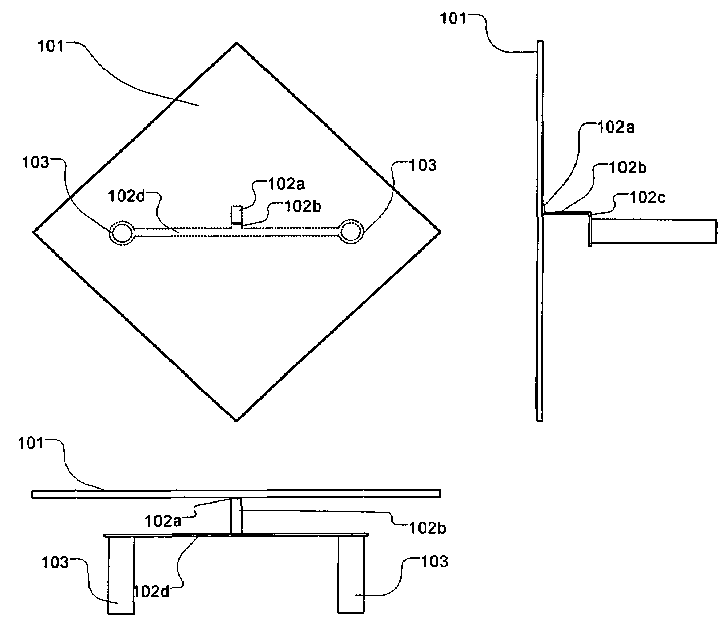
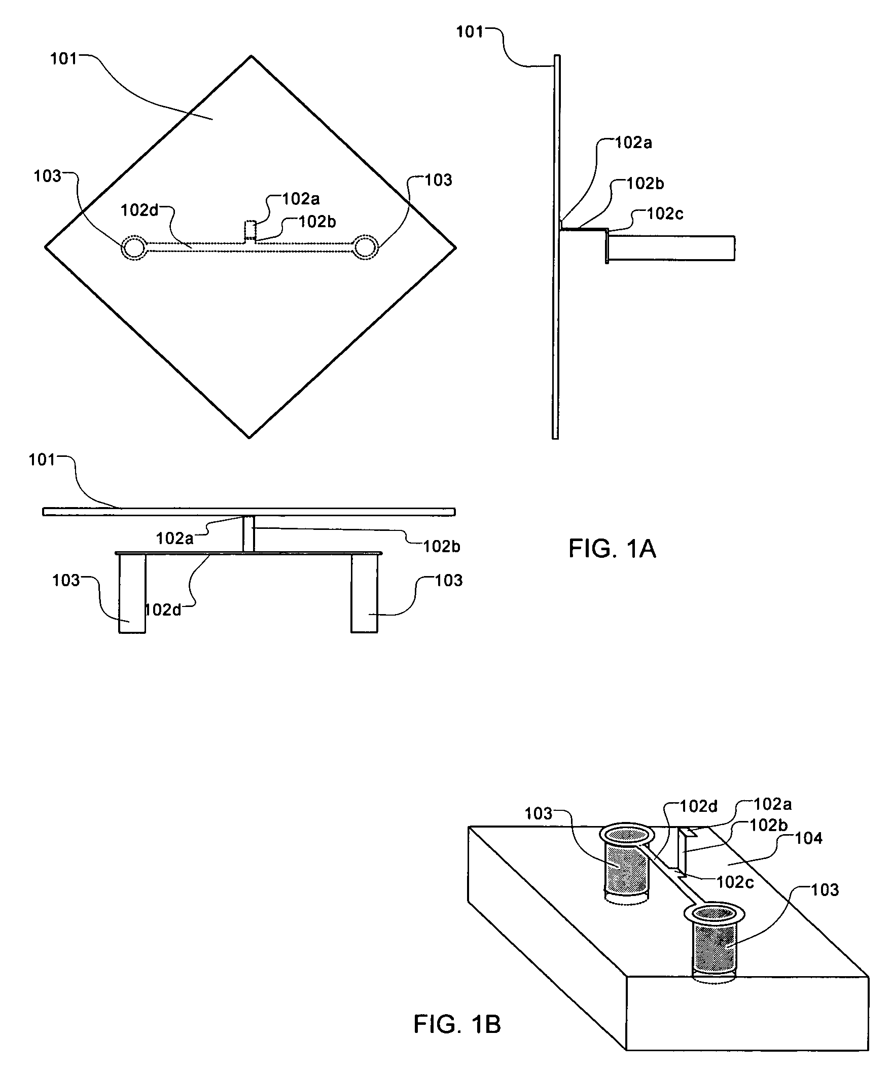
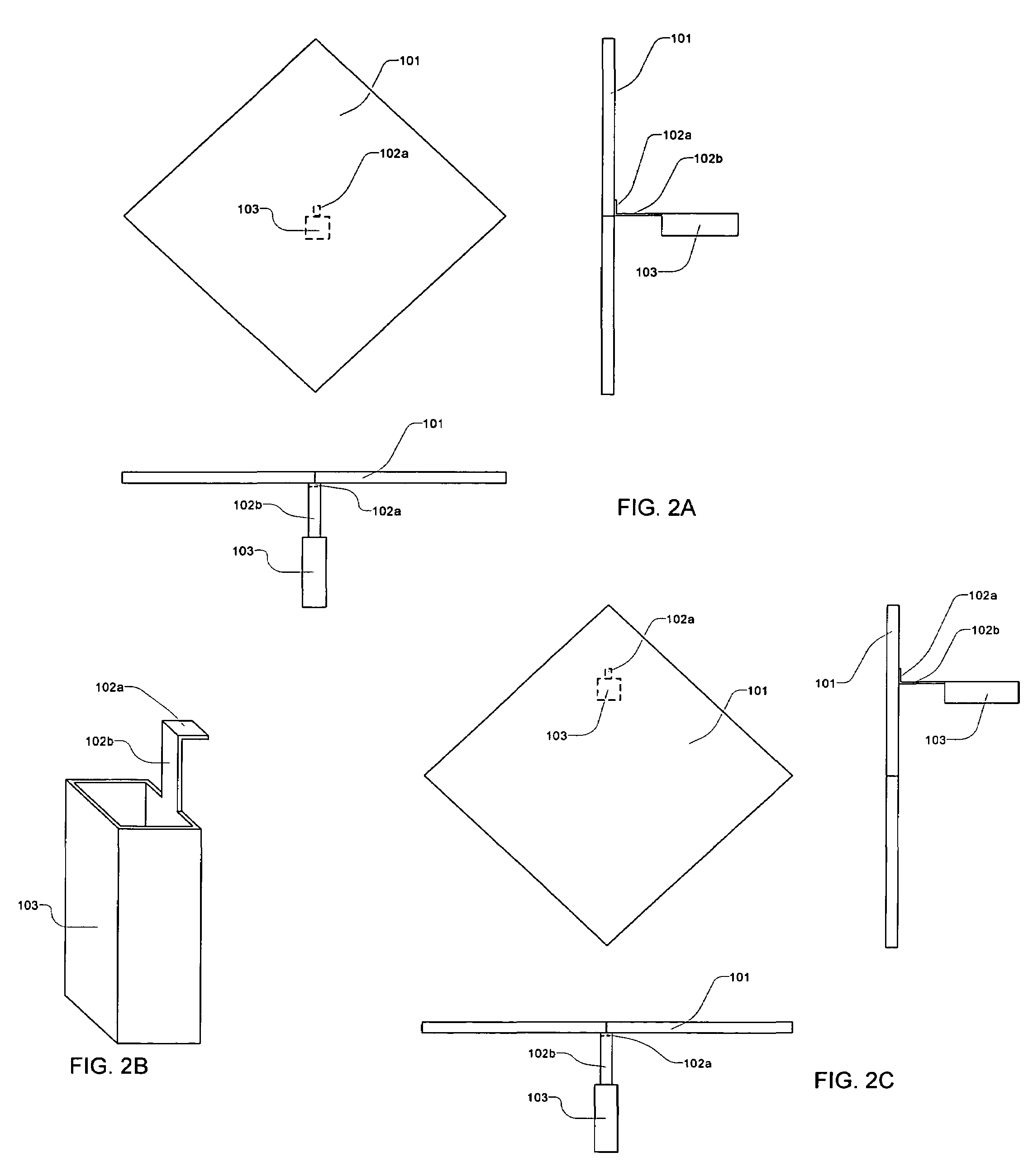
[0022]FIG. 1A shows top and side views of the hinge according to the present invention in the preferred embodiment. In this figure, hinge 102, best described as a compound torsion vertical cantilever, is composed of segments 102a, 102b, 102c and 102d. Segment 102a extends out parallel to the substrate surface and is connected directly to the surface of micro-mirror 101 opposite the substrate. Segment 102b extends out perpendicular to the substrate surface and is connected to segment 102a. The other end of segment 102b is connected to an extension (102c) of segment 102d. Segment 102d is itself a direct extension of support posts 103. Support posts 103 extend below the surface of the substrate (104) and anchor the compound hinge structure (102) to the substrate (104). The thickness of hinge 102 is small relative to the micro-mirror in order to ensure most of the bending occurs at the hinge. This improves the flatness of the micro-mirror in its deflected state. FIG. 1B shows a perspect...


PUM


Abstract

An improved hinge for a micro-mirror device composed of a conductive doped semiconductor and immune to plastic deformation at typical to extreme temperatures. The hinge is directly connected to the micro-mirror device and facilitates the manufacturing of an optically flat micro-mirror. This eliminates Fraunhofer diffraction due to recesses on the reflective surface of the micro-mirror. In addition, the hinge is hidden from incoming light thus improving contrast and fill-factor.

Description

TECHNICAL FIELD[0001]This invention relates to micro-mirror devices having one or more moveable elements that are moveable by means of a hinge.BACKGROUND ART[0002]The field of microelectromechanical systems (MEMS) has experienced an explosive growth during the last decade having found applications in accelerometers, pressure sensors, actuators and the miniaturization of various other mechanical devices. Electromechanical micromirror devices are an example of a MEMS device that has drawn considerable interest because of their application as spatial light modulators (SLMs).[0003]A spatial light modulator requires an array of a relatively large number of such micromirror devices. In general, the number of devices required ranges from 60,000 to several million for each SLM. A digital micro-mirror device (DMD) is one example of a micro-mechanical SLM. One or more hinges support each mirror and allow the mirrors to tilt. Images are formed by selectively tilting each mirror to reflect or n...

Claims


Application Information

Patent Timeline
Patent Type & Authority Patents(United States)
IPC IPC(8): G02B26/08
CPCG02B26/0841Y10S359/904G02B7/18G02B7/182
Inventor ISHII, FUSAO
Owner IGNITE INC
Why Eureka
Try Eureka