High speed circuits for electronic dispersion compensation

a high-speed circuit and electronic dispersion compensation technology, applied in the field of electronic circuits, can solve the problems of inter symbol interference (isi), bit errors in the receiver, and the concentration of signal power is degraded, so as to avoid or minimize the shortcomings

Active Publication Date: 2007-02-27
MACOM CONNECTIVITY SOLUTIONS LLC
View PDF9 Cites 23 Cited by
  • Summary
  • Abstract
  • Description
  • Claims
  • Application Information

AI Technical Summary

Benefits of technology

[0015]Therefore it is an object of the invention to provide a differential receiver circuit with e

Problems solved by technology

A well known impairment that degrades this concentration of signal power at the decision point in fiber optic communications systems is dispersion.
The received signal is affected by the sum of these components, resulting in inter symbol interference (ISI) by spreading the energy of each optical pulse over neighboring bits.
The dispersion can thus cause bit errors in the receiver by confusing 1s and 0s.
Dispersion is present in all optical systems, but its effects become worse over longer spans

Method used


Image

  • High speed circuits for electronic dispersion compensation
  • High speed circuits for electronic dispersion compensation
  • High speed circuits for electronic dispersion compensation

Examples


Embodiment Construction

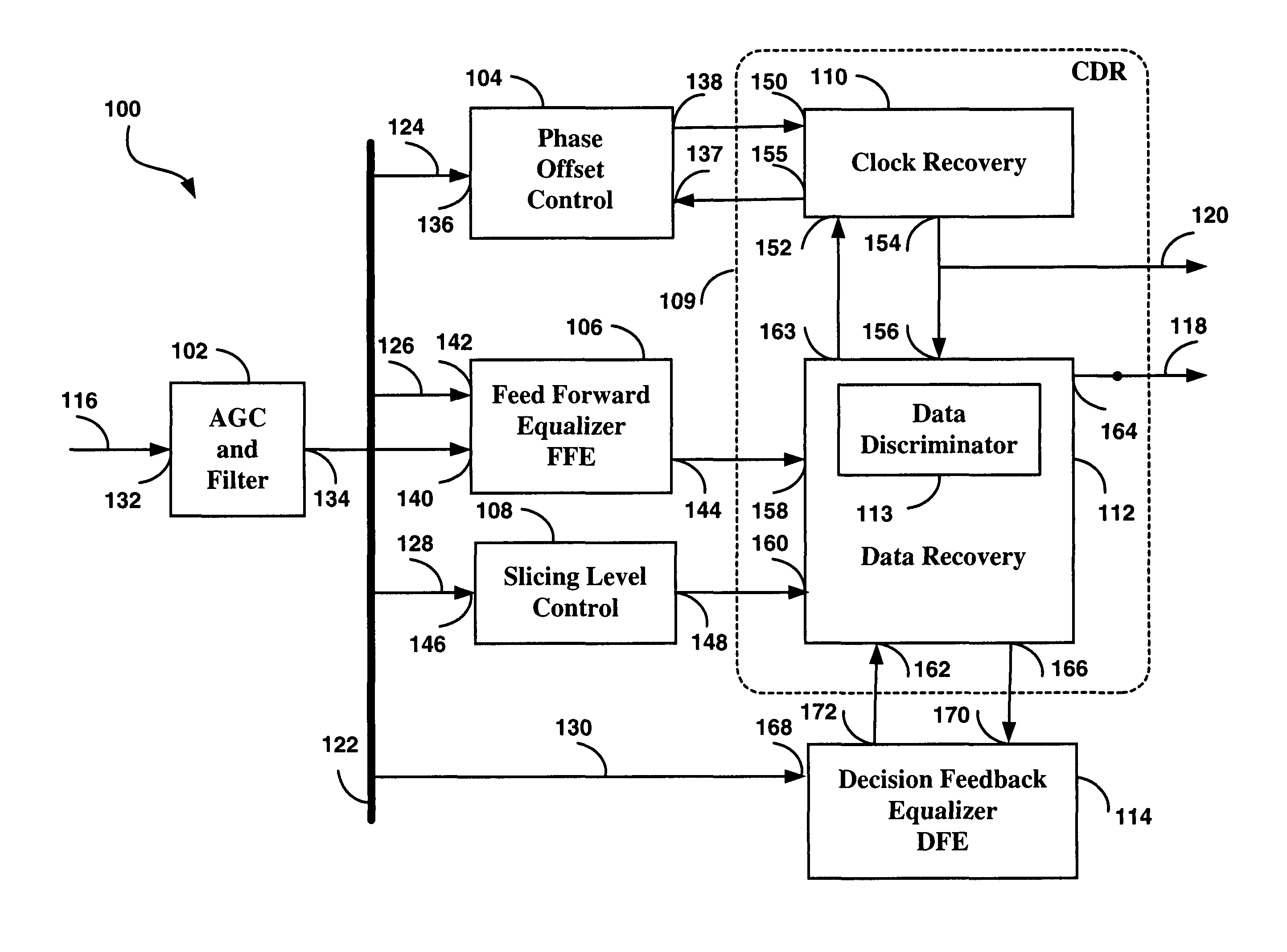
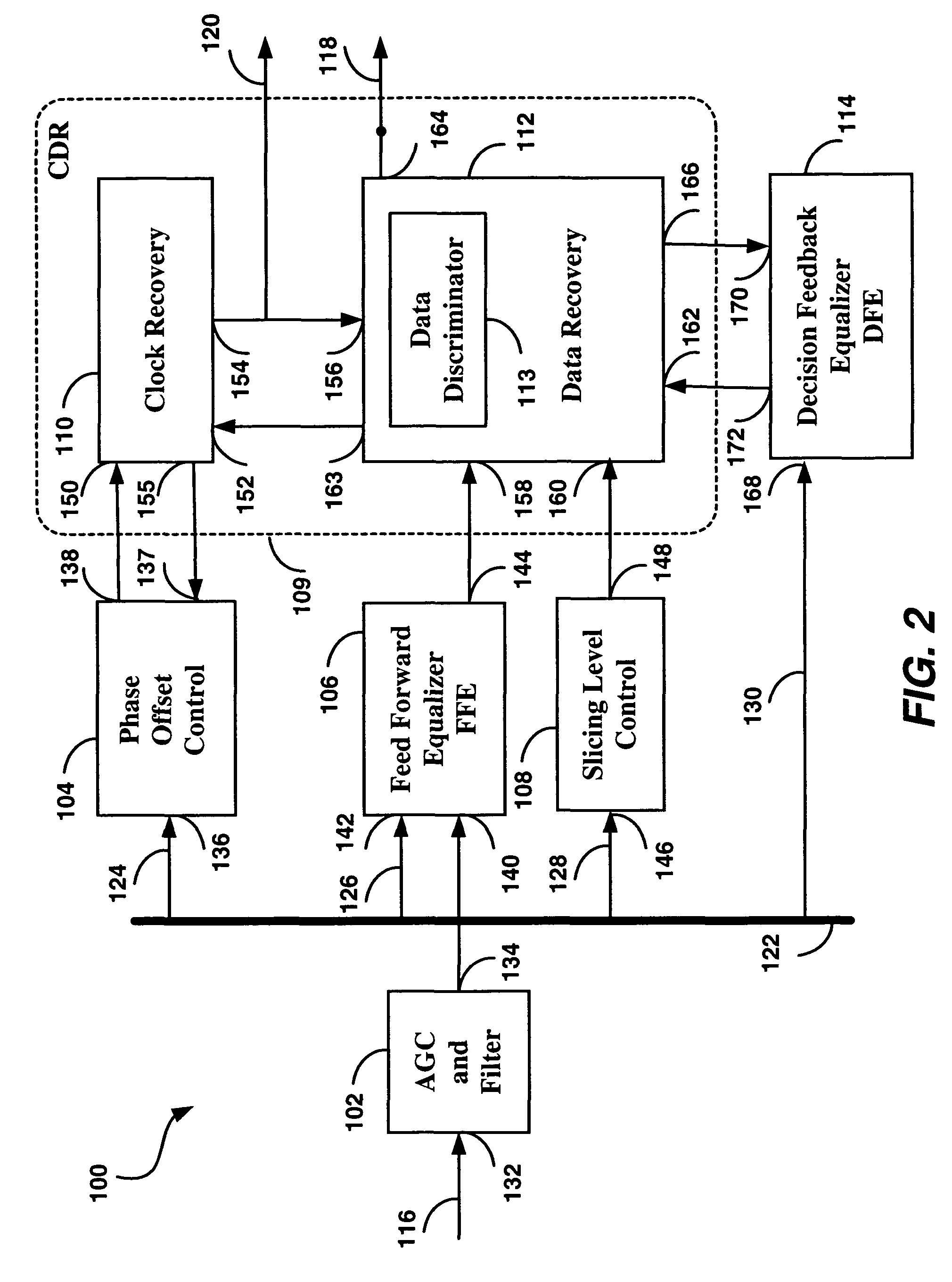
[0076]The embodiment of the invention is illustrated in FIG. 2 in the form of a system level block diagram. Each of the blocks of FIG. 2 is first briefly explained in terms of the system level functionality, and subsequently explained in more detail, with the aid of additional drawings.

[0077]Illustrated in FIG. 2 is the embodiment of an improved receiver circuit with electronic dispersion compensation (receiver circuit) 100, comprising an AGC and Filter block 102; a Phase Offset Control block 104; a Feed Forward Equalizer (FFE) 106; a Slicing Level Control block 108; a Clock and Data Recovery circuit (CDR) 109, comprised of a Clock Recovery block 110; a Data Recovery block 112; and a Decision Feedback Equalizer (DFE) 114.

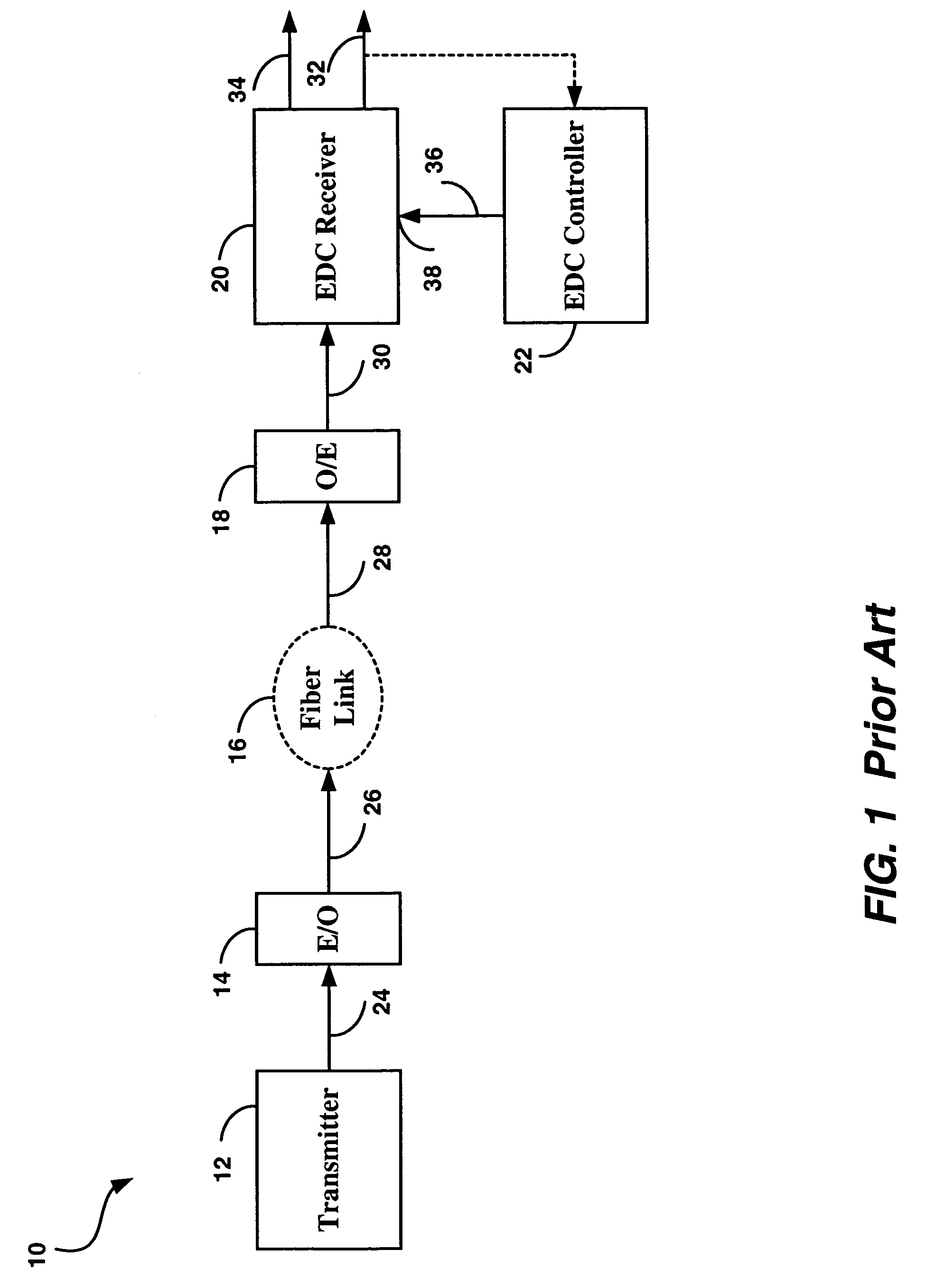
[0078]The receiver circuit 100 is intended to be used in a fiber optic communications system, in place of the EDC receiver 20 of FIG. 1, with improvements due to the design of the receiver circuit 100 providing better dispersion compensation (resulting in longer rea...


PUM


Abstract

The invention describes a number of differential, balanced high-speed circuits that permit the design of a receiver with Electronic Dispersion Compensation (EDC) on a single semiconductor substrate, including the functions of an analog Fast Forward Equalizer (FFE), a Clock and Data Recovery, a Decision Feedback Equalizer (DFE), enhanced by additional circuits that permit control of the slicing level to compensate for pulse distortion, and control of the phase offset to set the optimal eye sampling time when a distorted signal is received. To provide the high speed of operation, all circuits including the phase locked loop, operate as differential circuits, which include a number of improvements in the design of the charge pump, the decision feedback equalizer, the slicing level control, and others.

Description

RELATED APPLICATIONS[0001]The present application claims the benefit of U.S. Provisional Application Ser. No. 60 / 479,459 to Popescu et al, filed on Jun. 19, 2003, and entitled “High Speed Circuits for Electronic Dispersion Compensation (EDC)”.[0002]The present application is related to the U.S. patent application Ser. No. 10 / 638,387, entitled “A Differential Receiver Circuit with Electronic Dispersion Compensation”, invented by Popescu, Gradinaru et al., and the U.S. patent application Ser. No. 10 / 638,340, entitled “A Differential Receiver Circuit with Electronic Dispersion Compensation for Optical Communications Systems”, invented by Popescu, McPherson et al., filed concurrently herewith and incorporated herein by reference.FIELD OF THE INVENTION[0003]The invention relates to electronic circuits and, in particular, to high speed circuits for electronic dispersion compensation.BACKGROUND OF THE INVENTION[0004]In digital communications systems, the signal to noise ratio (SNR) is used...

Claims


Application Information

Patent Timeline
IPC IPC(8): H03H7/40H03H15/00H03L7/089H04B1/10H04B10/18H04L7/033H04L25/03H04L27/14
CPCH03H15/00H03L7/0896H04L7/033H04B10/2513H04L2025/0349H04L2025/03477
Inventor POPESCU, PETRETRAN, QUOC HAIMCPHERSON, DOUGLAS STUART
Owner MACOM CONNECTIVITY SOLUTIONS LLC
Why Eureka
Try Eureka