Processor isolation technique for integrated multi-processor systems

a multi-processor system and isolation technique technology, applied in the direction of functional testing, instruments, error detection/correction, etc., can solve the problems of cumbersome scheduling of external accesses to shared memory, inefficient access to external memory, cumbersome scheduling of external accesses to external memory, etc., to achieve faster debugging of complex multi-processor linked code. , the effect of simple structur

Inactive Publication Date: 2007-02-27
CISCO TECH INC
View PDF86 Cites 17 Cited by
  • Summary
  • Abstract
  • Description
  • Claims
  • Application Information

AI Technical Summary

Problems solved by technology

Access to an external memory is generally inefficient because the execution capability of each processor is substantially faster than its external interface capability; as a result, the processor often idles while waiting for the accessed data.
Moreover, scheduling of external accesses to a shared memory is cumbersome because the processors may be executing different portions of the program.
A drawback, however, is the difficulty in apportioning the algorithm into many different stages of equivalent duration.
Another drawback of the typical pipeline is the overhead incurred in transferring transient “context” data from one processor to the next in a high-bandwidth application.
Parallel processing of conventional data communications algorithms is not easily implemented with such a processor, so hardware processing engines are typically developed and implemented in application specific integrated circuits (ASIC) to perform various tasks of...

Method used


Image

  • Processor isolation technique for integrated multi-processor systems
  • Processor isolation technique for integrated multi-processor systems
  • Processor isolation technique for integrated multi-processor systems

Examples


Embodiment Construction

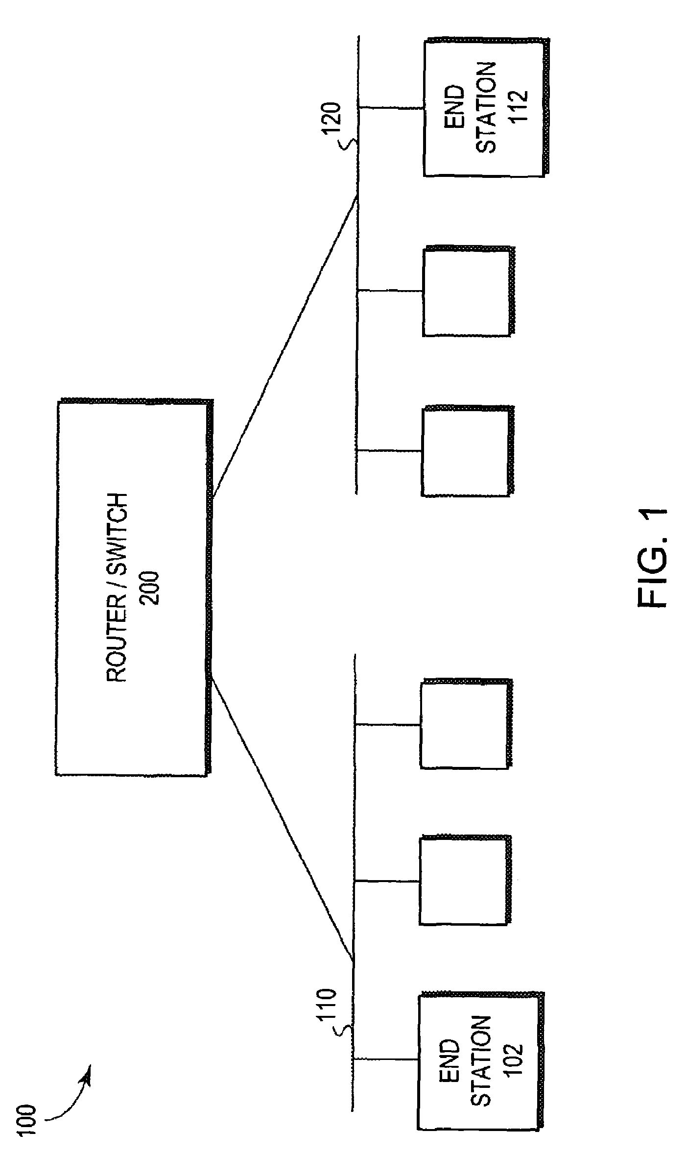
[0030]FIG. 1 is a block diagram of a computer network 100 comprising a collection of interconnected communication media and subnetworks attached to a plurality of stations. The stations are typically computers comprising end stations 102, 112 and intermediate station 200. The intermediate station 200 may be a router or a network switch, whereas the end stations 102, 112 may include personal computers or workstations. The subnetworks generally comprise local area networks (LANs) 110 and 120, although the invention may work advantageously with other communication media configurations such as point-to-point network links. Communication among the stations of the network is typically effected by exchanging discrete data frames or packets between the communicating nodes according to a predefined protocol. For the illustrative embodiment described herein, the predefined protocol is the Internet protocol (IP), although the invention could be implemented with other protocols, such as the Int...


PUM


Abstract

A processor isolation technique enhances debug capability in a multiprocessor circuit. A bypass register has a bit location which may indicate that a processor is to be bypassed. A code entry point is selected to permit a downstream processor to do the work of the bypassed processor. The processors may be arrayed in a pipeline.

Description

CROSS-REFERENCE TO RELATED APPLICATION[0001]The present application is a continuation of U.S. patent application Ser. No. 09 / 432,526, now issued as U.S. Pat. No. 6,681,341, which was filed on Nov. 3, 1999, by William Fredenburg et al.FIELD OF THE INVENTION[0002]The present invention relates generally to a programmable arrayed processing engine of a network switch and more particularly, to a method and apparatus for debugging failures of processors within a programmable arrayed processing engine.BACKGROUND OF THE INVENTION[0003]Computer architecture generally defines the functional operation, including the flow of information and control, among individual hardware units of a computer. One such hardware unit is a processing engine that contains arithmetic and logic processing circuits organized as a set of data paths. In some implementations, the data path circuits may be configured as a processor having operations that are defined by a set of instructions. The instructions are typica...

Claims


Application Information

Patent Timeline
IPC IPC(8): G06F11/00G06F11/27
CPCG06F11/2242
Inventor FREDENBURG, WILLIAMKEY, KENNETH MICHAELWRIGHT, MICHAEL L.MARSHALL, JOHN WILLIAM
Owner CISCO TECH INC
Why Eureka
Try Eureka