
Double vacuum bag process for resin matrix composite manufacturing

a technology of resin matrix and vacuum bag, applied in the direction of chemistry apparatus and processes, hollow wall articles, other domestic objects, etc., can solve the problem of inability to achieve, achieve precise net shape control, reduce void content, and enhance mechanical properties and performances

Inactive Publication Date: 2007-03-06
NASA
View PDF2 Cites 50 Cited by
  • Summary
  • Abstract
  • Description
  • Claims
  • Application Information

AI Technical Summary

Benefits of technology

The DVB process consistently produces high-quality, void-free composite laminates with enhanced mechanical properties by effectively managing volatiles and resin fluidity, surpassing traditional single-vacuum-bag techniques.

Problems solved by technology

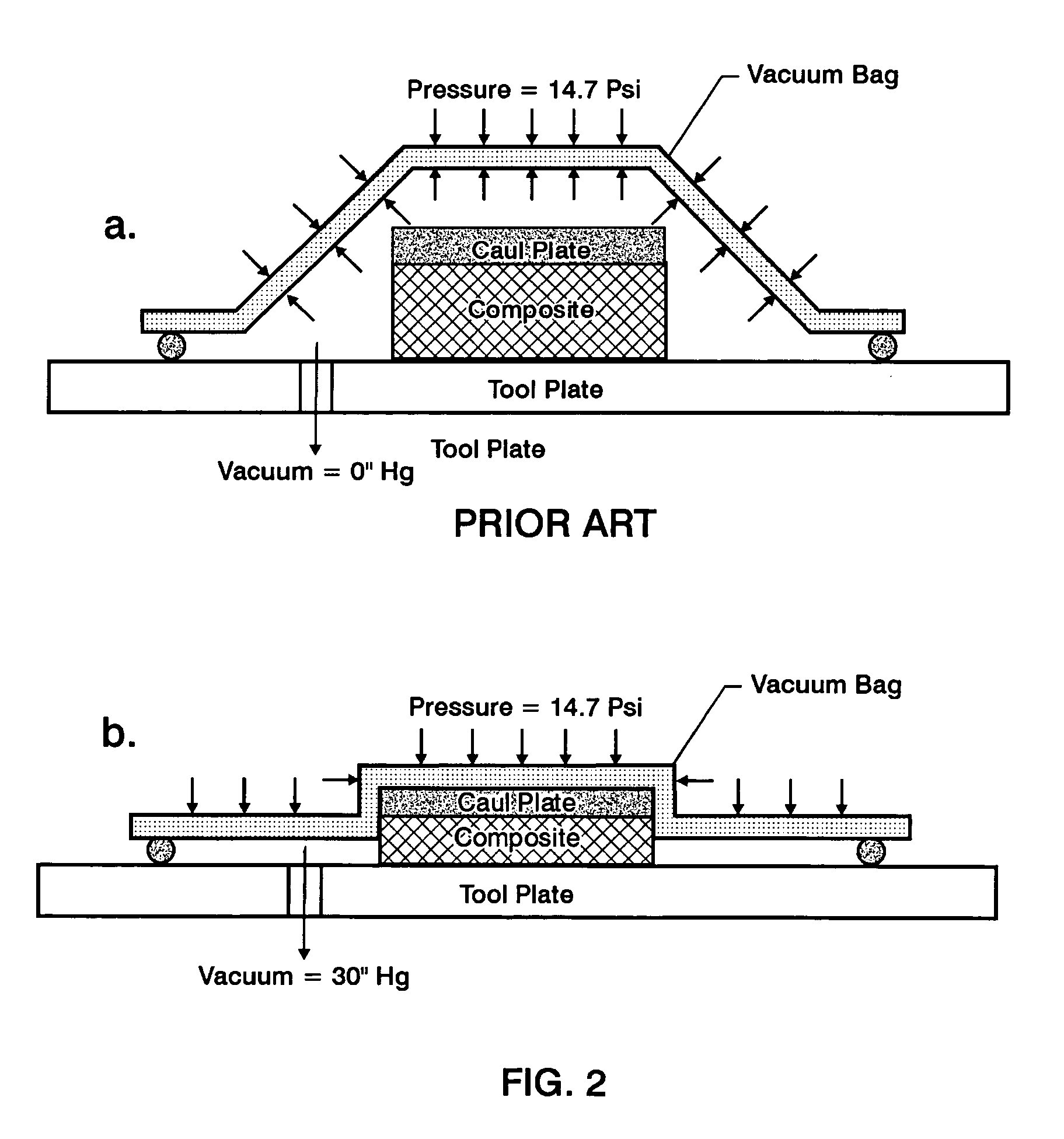
During single vacuum bag techniques, this would not be possible since the inner bag would be compacted around the composite.

Method used


Image

  • Double vacuum bag process for resin matrix composite manufacturing
  • Double vacuum bag process for resin matrix composite manufacturing
  • Double vacuum bag process for resin matrix composite manufacturing

Examples


Embodiment Construction

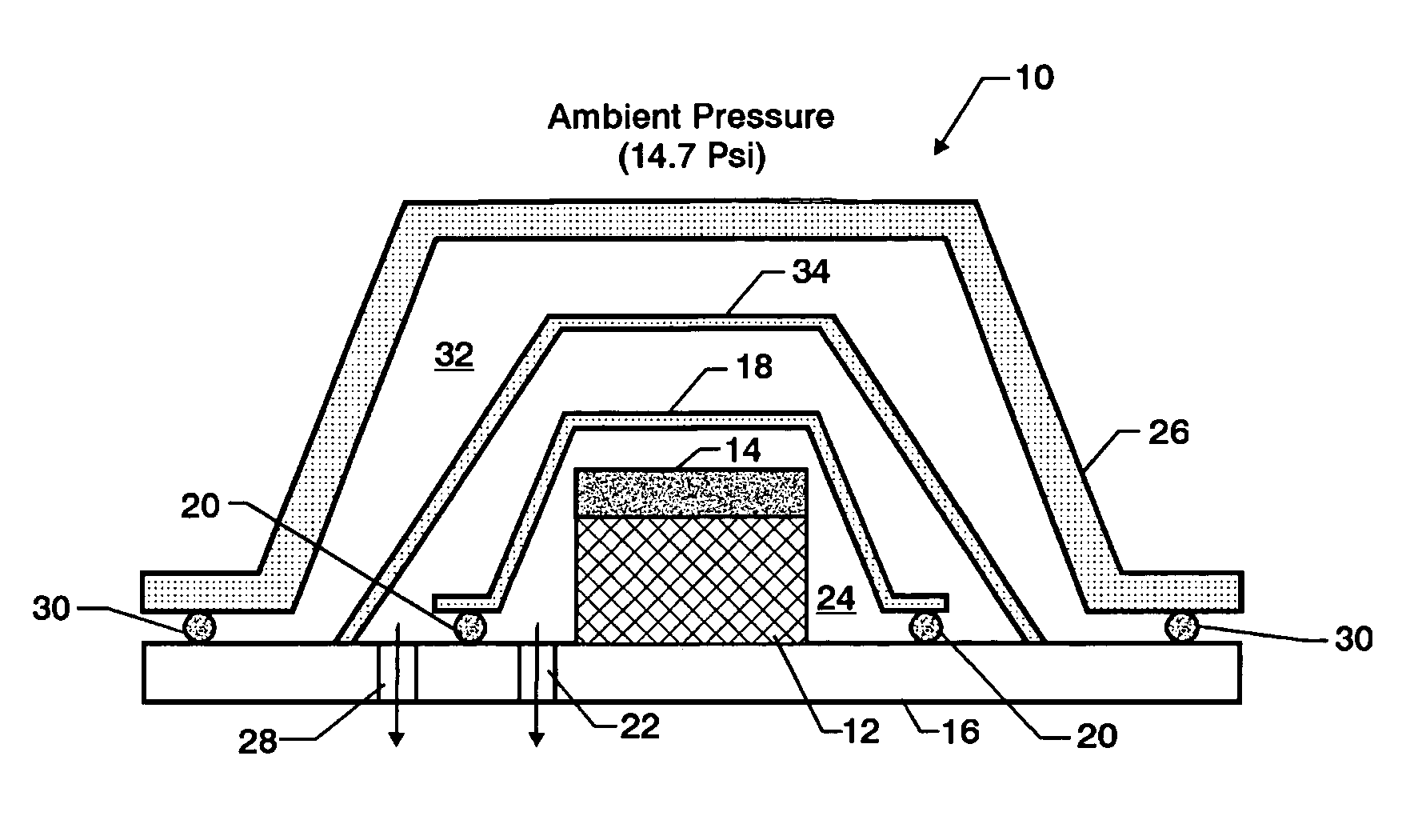
[0026]The schematic drawing shown in FIG. 3 is of a double vacuum bag (DVB) molding assembly 10 for composite manufacturing. A composite 12 illustrated as fiber reinforced reactive resin matrix prepregs are laid up between a caul plate 14 and a tool plate 16. The caul and tool plates 14, 16 may be constructed of steel or other appropriate material.

[0027]A first barrier, such as a vacuum bag 18 (designated as inner bag), encloses the caul plate 14 and composite 12 relative to the tool plate 16 and is sealed by one or more seals 20 relative to the tool plate 16. A first vacuum port 22 is preferably built through the tool plate 16 or otherwise provided to communicate the interior 24 with a vacuum pump (not shown) to provide a first environment.

[0028]A second barrier, or bag 26 (designated as the outer bag) is preferably assembled in a somewhat similar fashion, with a second vacuum port 28 located intermediate to the seals 20 connecting the first bag 18 to the tool plate 16 and the seal...


PUM

PropertyMeasurementUnit
molar ratioaaaaaaaaaa
temperatureaaaaaaaaaa

Abstract

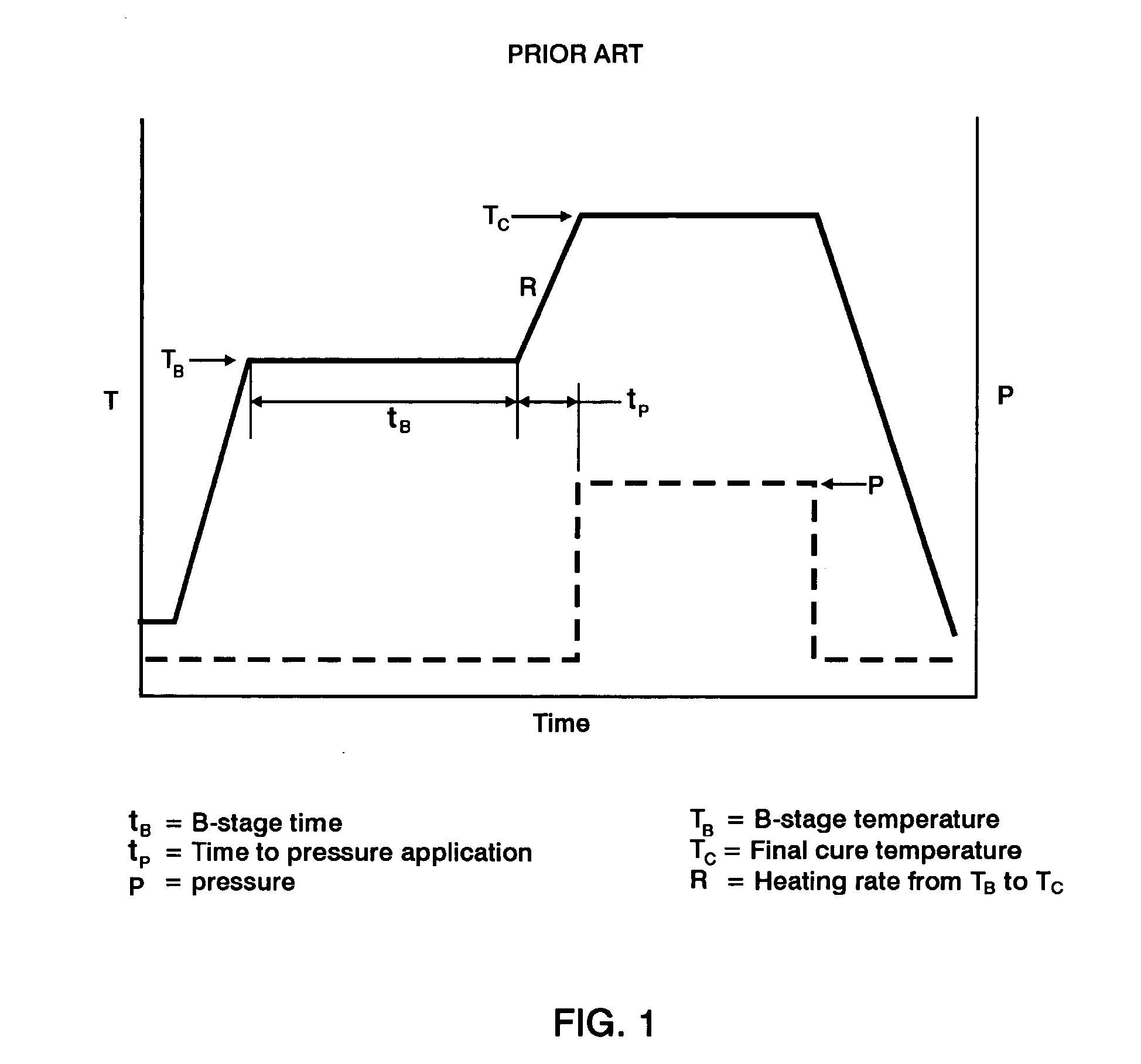
A double vacuum bag molding assembly with improved void management and laminate net shape control which provides a double vacuum environment for use in fabricating composites from prepregs containing air and / or volatiles such as reactive resin matrix composites or composites from solvent containing prepregs with non-reactive resins matrices. By using two vacuum environments during the curing process, a vacuum can be drawn during a B-stage of a two-step cycle without placing the composite under significant relative pressure. During the final cure stage, a significant pressure can be applied by releasing the vacuum in one of the two environments. Inner and outer bags are useful for creating the two vacuum environments with a perforated tool intermediate the two. The composite is placed intermediate a tool plate and a caul plate in the first environment with the inner bag and tool plate defining the first environment. The second environment is characterized by the outer bag which is placed over the inner bag and the tool plate.

Description

CLAIM OF BENEFIT OF PROVISIONAL APPLICATION[0001]This application claims the benefit of U.S. Provisional Patent Application No. 60 / 571,954 filed May 13, 2004.ORIGIN OF THE INVENTION[0002]This invention described herein was made by employees of the United States Government and may be manufactured and used by or for the Government of the United States of America for governmental purposes without the payment of any royalties thereon or therefor.BACKGROUND OF THE INVENTION[0003]Polymer matrix composites are comprised of the sub-groups of reactive matrix composites and non-reactive matrix composites. Reactive matrix composites typically produce low molecular weight volatiles during curing. Non-reactive matrix composites, also commonly referred to as thermoplastics, are generally high molecular weight structures which are heated to flow and then cooled to cure. When laying up composites prior to curing, adjacent layers may entrap air pockets in between. Additionally, during the curing pro...

Claims


Application Information

Patent Timeline
Patent Type & Authority Patents(United States)
IPC IPC(8): B29C51/10B29C51/42B29C35/00B29C35/02B29C70/44
CPCB29C35/02B29C37/0064B29C70/44
Inventor HOU, TAN-HUNGJENSEN, BRIAN J.
Owner NASA
Learn More