Method and process for co-combustion in a waste to-energy facility

a waste to energy facility and co-combustion technology, applied in the direction of combustion types, greenhouse gas reduction, furnaces, etc., can solve the problems of huge waste disposal prices, high toxic levels of emissions originating from waste, and high price for everything, so as to reduce the chance of dioxin reformation in the boiler and the effect of high degree of scrubbing

Inactive Publication Date: 2007-03-13
GREEN ISLAND ENVIRONMENTAL +1
View PDF15 Cites 20 Cited by
  • Summary
  • Abstract
  • Description
  • Claims
  • Application Information

AI Technical Summary

Benefits of technology

[0032]In the Dry Scrubbing (New Precalciner) System a cement precalciner can be used for dry scrubbing of the acid gases of waste co-combustion flue gases. This scrubbing process can generally achieve extremely high degree of scrubbing and acidic gas emission such as SO2 can be less than 8 ppm. This is because there is more than a hundred times of the theoretically required lime dust suspended in the system ‘hunting’ for acidic gases. The successful removal of acidic gases, particularly hydrogen chloride, can greatly reduce the chances of reformation of dioxin in the boiler. In addition, the boiler tubes of the waste heat boiler can last much longer, thereby providing higher availability of the steam generation system. Hot gas from the secondary combustion chamber entering the precalciner can provide part of the energy required to calcinate the fine raw cement mix. The balance of the energy required may come from a Marpol oil burner, for example. The dry scrubbing process typically takes place at 900° C. to 950° C.

Problems solved by technology

Even as society progresses economically and socially there is still a price for everything and among these are the huge prices incurred for waste disposal.
In a conventional (or dedicated) incineration plant the waste is burnt at a relatively low temperature and emissions originating from the waste are comparatively high in toxic levels.

Method used


Image

  • Method and process for co-combustion in a waste to-energy facility

Examples


Embodiment Construction

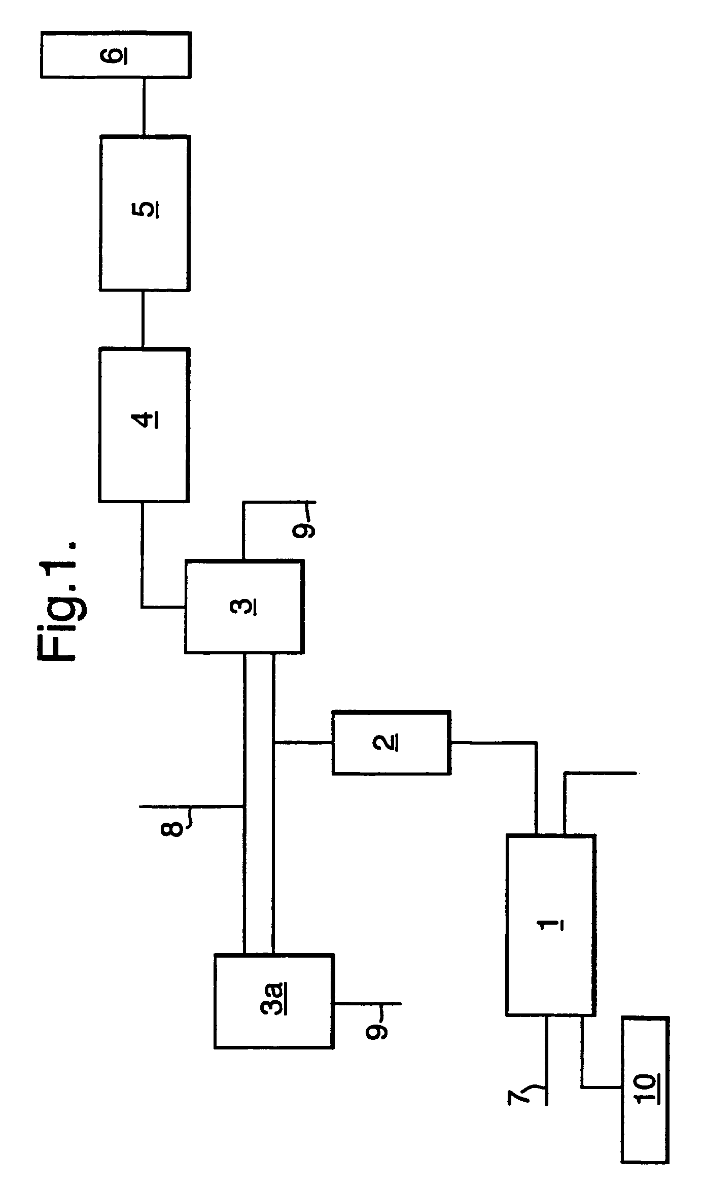
[0051]One embodiment of the co-combustion process, which is the possibility of merging hot gas evolved from the clinker cooling process into the mass burn system for Municipal Solid Waste (MSW) and industrial waste, is described below with reference to the FIGURE.

[0052]As shown by stream #7, solid waste can be fed into an incineration system comprising a rotary dryer and incinerator where drying and combustion of the solid waste can occur. A controlled amount of hot gas input typically at a temperature of about 240° C. from the cement grate cooler system can be routed into the mass burn unit as shown by stream #10.

[0053]The flue gas from the drying and incineration system (#1) can be further heated up in a Secondary Combustion Chamber (#2). The target temperature in the Secondary Combustion Chamber can be as high as 1200° C., generally by using additional fuel (coal / natural gas / oil), and this high temperature in combination with intensive turbulence and long retention time can lead ...


PUM

PropertyMeasurementUnit
temperatureaaaaaaaaaa
retention timeaaaaaaaaaa

Abstract

The co-combustion process may comprise the following unit operations: routing of hot gas (10) generated in the clinker cooling process to a rotary kiln (1); use of part of the rotary kiln exhaust gas to dry solid wastes in rotary dryers; leading the gases from both the dryer and the combustion kiln to the secondary combustion chamber (2); use of additional fuel to boost up the secondary combustion chamber reaction temperature to as high as 1200° C.; primary dry gas scrubbing in a precalciner or precalciners (3, 3a); heat recovery (4) and power generation; secondary gas scrubbing (5) in a semi-dry scrubber; bag filtering after activated carbon injection and returning of all the collected ash and used carbon into the waste kiln and / or a cement kiln. Detrimental materials for cement processing generated by waste combustion can be by-passed to a scrubbing system and a cement kiln. Residue slag from waste kilns can be treated and reused.

Description

BACKGROUND OF THE INVENTION[0001]1. Field of the Invention[0002]The present invention relates to a method of integrating the cement production process with mass burn technology by way of merging the hot gas evolved from the cement kiln into a mass burn system typified by incineration of municipal solid waste and industrial wastes in a rotary kiln.[0003]2. Description of the Related Art[0004]Even as society progresses economically and socially there is still a price for everything and among these are the huge prices incurred for waste disposal. Along with the higher standards of living the amount of waste requiring disposal have been increasing at an alarming rate especially in developed countries. Although measures have been in place including source reduction and recycling to reduce waste generated by a community, a major portion of the waste still needs to be disposed of in landfills and incineration. Waste incineration plants have been widely accepted and waste burning in cement ...

Claims


Application Information

Patent Timeline
Patent Type & Authority Patents(United States)
IPC IPC(8): F27B15/00F27B27/02C04B2/10C04B7/43C04B7/44F23G5/00F23G5/16F23G5/20F23G5/46
CPCC04B7/43C04B7/4407C04B2290/20F23G5/006F23G5/16F23G5/20F23G5/46F23G2201/303F23G2202/103F23G2203/20F23G2206/201F23G2900/50001F23J2219/60Y02E20/12Y02E20/30Y02P40/121F23G5/00
Inventor LEUNG, CHING CHIUAUNG, KHINECHEUNG, WAI MAN
Owner GREEN ISLAND ENVIRONMENTAL
Why Eureka
Try Eureka