Grounding brush for mitigating electrical current on motor shafts

a technology of motor shaft and grounding brush, which is applied in the direction of relays, instruments, record information storage, etc., can solve the problems of high common mode voltage (cmv), shaft induced current, and buildup of charge on the shaft surface, so as to reduce the current of the shaft of the electric motor and achieve the effect of effective conductive brush assembly

Active Publication Date: 2007-03-20
ILLINOIS TOOL WORKS INC
View PDF22 Cites 99 Cited by
  • Summary
  • Abstract
  • Description
  • Claims
  • Application Information

AI Technical Summary

Benefits of technology

[0012]An advantage of the present invention is providing an effective conductive brush assembly to reduce shaft current on electric motors.
[0013]Another advantage of the present invention is providing a grounding device for electric motors that functions effectively for a prolonged period of time without service, maintenance or repair.
[0014]Still another advantage of the present invention is providing a conductive brush system having improved conductiv...

Problems solved by technology

A drawback to the use of AC motors with variable speed drives is that higher common mode voltage (CMV) is generated by the variable speed drive that increases shaft induced currents.
While the motor is running, the bearings become more resistive to current flow, causing a buildup of charge on the shaft surfaces.
This discharge causes electric discharge machining (EDM), which can damage the surfaces of the bearing races and the balls in the bearing.
Both the fusion crater and the particulate material in the bearing act to disturb the free flow rotation of the bearin...

Method used


Image

  • Grounding brush for mitigating electrical current on motor shafts
  • Grounding brush for mitigating electrical current on motor shafts
  • Grounding brush for mitigating electrical current on motor shafts

Examples


Embodiment Construction

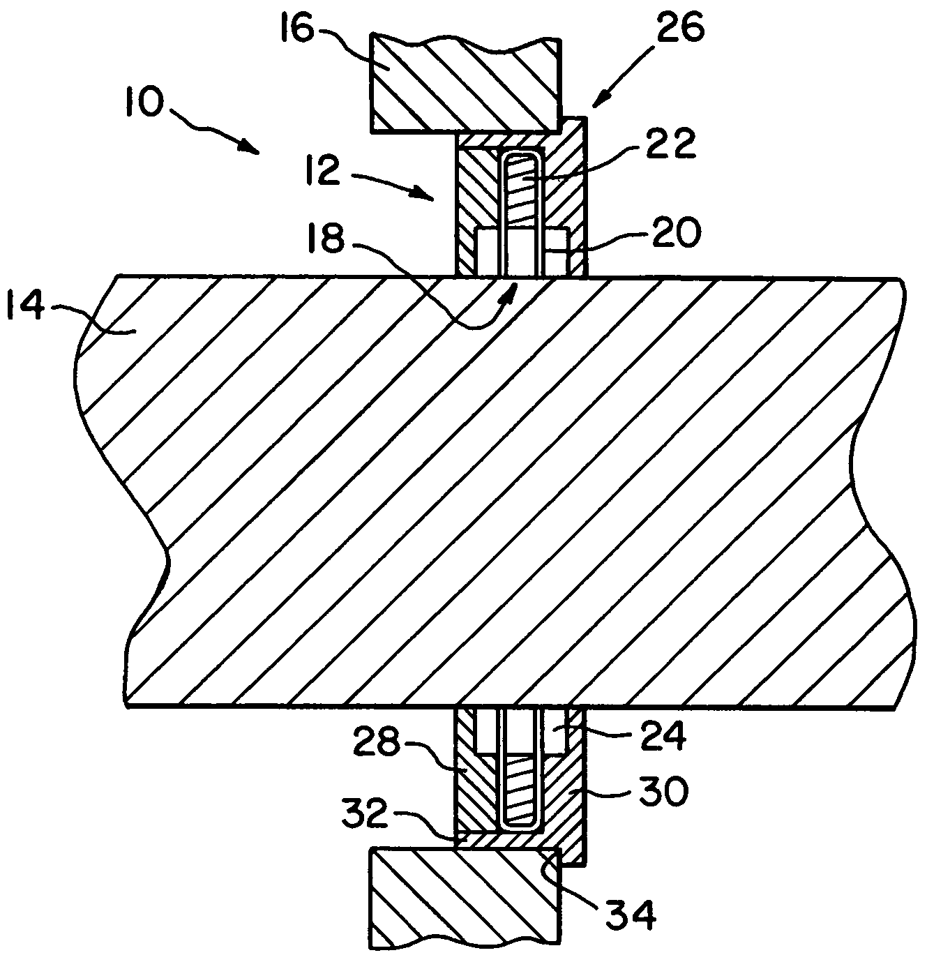
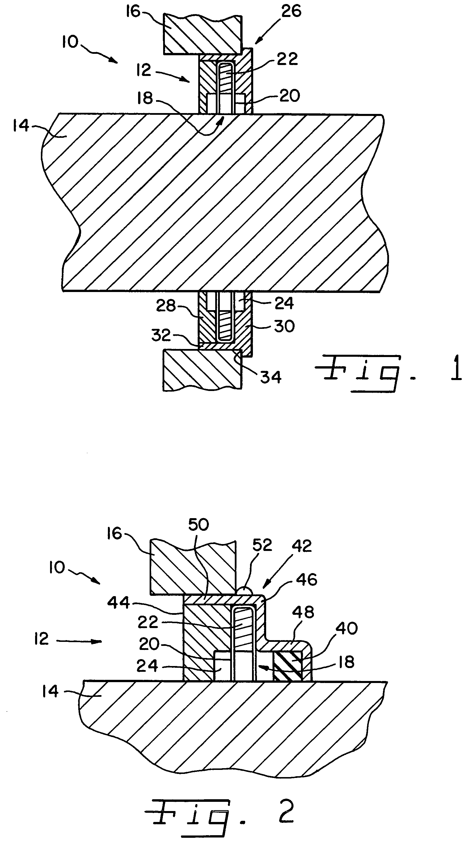
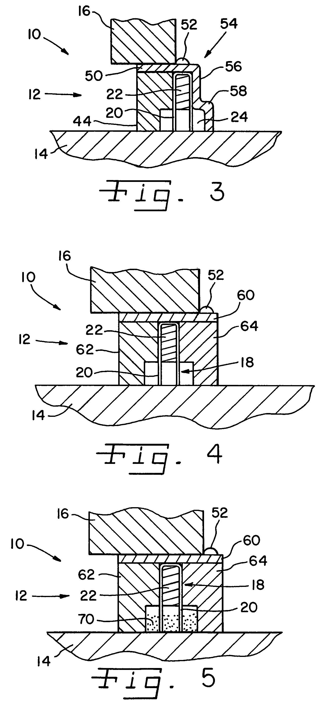
[0026]Referring now more specifically to the drawings, and to FIG. 1 in particular, numeral 10 designates an electric motor, in fragmentary view, having a shaft charge dissipating assembly 12 in accordance with the present invention operatively associated with a motor shaft 14 of motor 10. Charge dissipating assembly 12 is readily adaptable for use on motors 10 of various sizes, having motor shafts 14 of various diameters.

[0027]Charge dissipating assembly 12 is annular in shape, surrounding shaft 14. Charge dissipating assembly 12 is operatively arranged between shaft 14 and a part of a housing of the motor, such as motor faceplate 16. Assembly 12 is continuously operative to dissipate static charges that build on motor shaft 14 during operation of motor 10.

[0028]Charge dissipating assembly 12 includes a brush assembly 18 having a plurality of individual fiber filaments 20 that may be arranged individually or in bundles circumferentially around shaft 12. Each filament 20 is a fine, ...


PUM


Abstract

A grounding brush for mitigating static electric charge on a motor shaft includes a plurality of filaments secured to an annular frame around the shaft, with tips of the filaments disposed in a channel defined by the frame. Conductive powder can be provided in the channel to improve current flow from the shaft to the filaments.

Description

CROSS-REFERENCE TO RELATED APPLICATIONS[0001]The present application claims the benefits of U.S. Provisional Application Ser. No. 60 / 508,949, filed Oct. 6, 2003 and U.S. Provisional Application Ser. No. 60 / 508,950, also filed Oct. 6, 2003; and, further, the present application is a continuation-in-part of co-pending U.S. application Ser. No. 10 / 714,295, filed on Nov. 14, 2003 which claims the benefit of U.S. Provisional Application Ser. No. 60 / 455,301, filed on Mar. 17, 2003.FIELD OF THE INVENTION[0002]The present invention relates to grounding devices for controlling shaft current that is generated in AC motors controlled by variable speed drives or DC motors, and, more specifically, to non-contacting grounding devices.BACKGROUND OF THE INVENTION[0003]Shaft induced electrical current is experienced in electrical motors, and is commonly experienced with three-phase motors driven by variable speed drives.[0004]Variable speed drives utilize pulse width modulation technology to vary th...

Claims


Application Information

Patent Timeline
IPC IPC(8): H01H47/00H05F3/00H05F3/02H02H1/00H02H1/04H02H3/22H02K5/16G11B19/20H02K5/14H02K5/22H02K11/00H05F3/04
CPCG11B19/2009H05F3/04H05F3/02H02K11/0089H02K11/40
Inventor OH, HIEYOUNG W.KING, CHARLES A.
Owner ILLINOIS TOOL WORKS INC
Why Eureka
Try Eureka