Hydraulic drill bit assembly

a drill bit and hydraulic technology, applied in the field of drill bits, can solve the problems of drilling bit damage, drill bit vibration, drill bit damage, etc., and achieve the effects of reducing the vibration of the tool string, reducing the whirl of the bit, and reducing the wear fel

Active Publication Date: 2007-04-03
SCHLUMBERGER TECH CORP
View PDF58 Cites 80 Cited by
  • Summary
  • Abstract
  • Description
  • Claims
  • Application Information

AI Technical Summary

Benefits of technology

[0012]In embodiments where hydraulic pressure moves the shaft, the position of the shaft depends on the pressures within the first and second sections as well as the formation pressure of the subterranean formation if the distal end of the shaft is in contact with the formation. In soft subterranean formations, the distal end may travel a maximum distance into the formation, in such an embodiment the shaft may stabilize the drill bit assembly as it rotates reducing vibrations of the tool string. In harder formations the compressive strength of the formation may resist the axial and / or rotational movement of the shaft. In such an embodiment, the jackleg apparatus may absorb some of the formation's resistance and also transfer a portion of the resistance to the tool string through the first section of the hydraulic compartment. In such embodiments, at least a portion of the weight of the tool string will be loaded to the shaft focusing the weight of the tool string immediately in front of the distal end of the shaft and thereby penetrating a portion of the subterranean formation. Since at least a portion of the weight of the tool string is focused in the distal end, bit whirl may be minimized even in hard formations. In such a situation, depending on the geometry of the distal end of the shaft, the distal end may force a portion of the subterranean formation outward placing it in a path of the cutting elements.
[0013]Still referring to embodiments where the hydraulic pressure moves the shaft, another useful result of loading the shaft with the weight of the tool string is that it subtracts some of the load felt by the working portion of the drill bit assembly. By subtracting the load on the working portion automatically through the jackleg apparatus when an unknown hard formation is encountered, the cutting elements may avoid sudden impact into the hard formation which may potentially damage the working portion and / or the cutting elements.
[0014]In embodiments where the hydraulic pressure moves the working portion of the assembly, loading weight of the tool string to the shaft allows precise metering of the actual weight loaded to the working portion that may be monitored from the surface over a downhole network. This allows the weight loaded to the working portion to be controlled accurately because formation pressures and characteristics may be sensed and accounted for in real-time.
[0015]The shaft may be disposed within a sleeve that is rotationally isolated from the body portion. The shaft and / or its distal end may also be rotationally isolated from the body portion of the drill bit assembly. Rotational isolation may reduce the wear felt by the distal end of the shaft and prolong its life. The distal end of the shaft may comprise a superhard material. Such a material may be diamond, polycrystalline diamond, boron nitride, or a cemented metal carbide. The shaft may also comprise a wear resistant material such a cemented metal carbide, preferably tungsten carbide.

Problems solved by technology

Often drill bits are subjected to harsh conditions when drilling below the earth's surface.
Replacing damaged drill bits in the field is often costly and time consuming since the entire downhole tool string must typically be removed from the borehole before the drill bit can be reached.
Bit whirl in hard formations may result in damage to the drill bit and reduce penetration rates.
Further loading too much weight on the drill bit when drilling through a hard formation may exceed the bit's capabilities and also result in damage.
Too often unexpected hard formations are encountered suddenly and damage to the drill bit occurs before the weight on the drill bit can be adjusted.
A low whirling frequency accompanied by a high acceleration magnitude based on empirically established values is associated with destructive vibration of the drilling component.

Method used


Image

  • Hydraulic drill bit assembly
  • Hydraulic drill bit assembly
  • Hydraulic drill bit assembly

Examples


Embodiment Construction

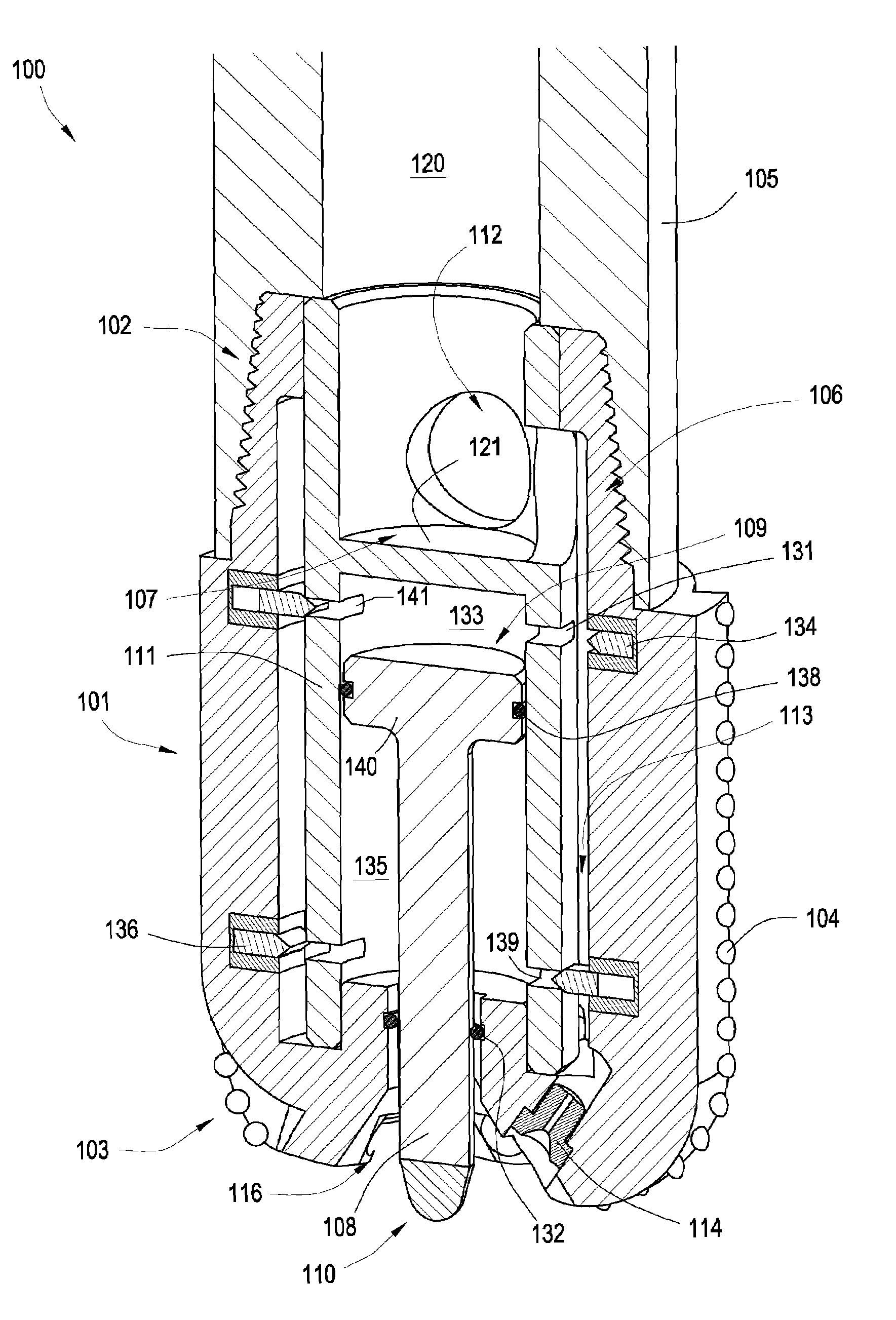
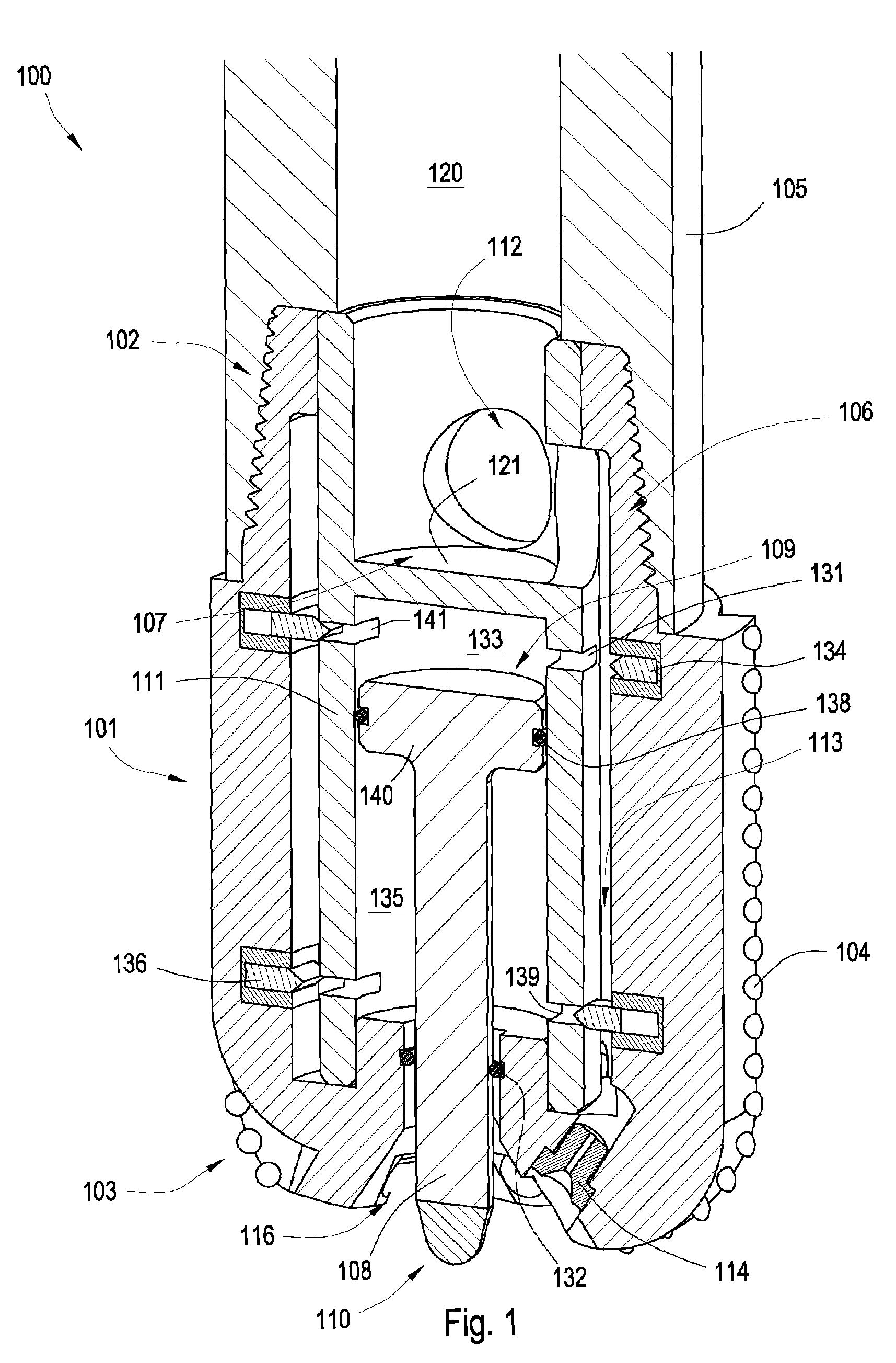
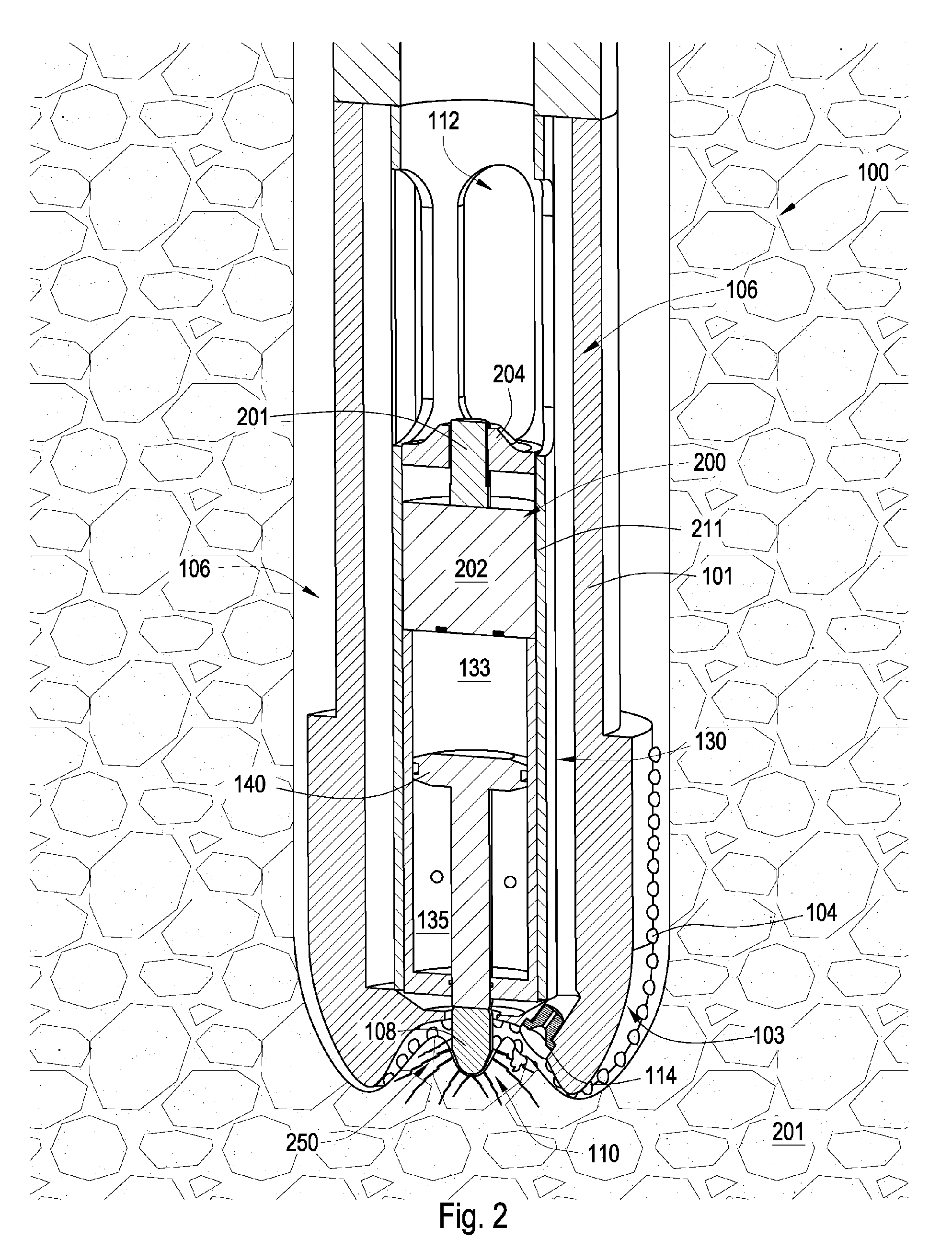
[0039]FIG. 1 is a cross sectional diagram of an embodiment of a drill bit assembly 100. The drill bit assembly 100 comprises a body portion 101 intermediate a shank portion 102 and a working portion 103. In this embodiment, the shank portion 102 and body portion 101 are formed from the same piece of metal although the shank portion 102 may be welded or otherwise attached to the body portion 101. The working portion 103 comprises a plurality of cutting elements 104. In other embodiments, the working portion 103 may comprise cutting elements 104 secured to a roller cone or the drill bit assembly 100 may comprise cutting elements 104 impregnated into the working portion 103. The shank portion 102 is connected to a downhole tool string component 105, such as a drill collar, drill pipe, or heavy weight pipe, which may be part of a downhole tool string used in oil, gas, and / or geothermal drilling.

[0040]A reactive jackleg apparatus 106 is generally coaxial with the shank portion 102 and di...


PUM


Abstract

In one aspect of the present invention a drill bit assembly has a body portion intermediate a shank portion and a working portion. The working portion has at least one cutting element and the body portion has at least a portion of a jackleg apparatus. The jackleg apparatus has at least a portion of a shaft disposed within a chamber; the shaft has a distal end. The jackleg apparatus has a hydraulic compartment adapted to displace the distal end of the shaft relative to the working portion. The chamber also has an opening proximate the working portion of the assembly. The hydraulic compartment may be part of a hydraulic circuit which has a pump. The pump may have a first section with is rotationally fixed to the body portion and a second section rotationally isolated from the body portion.

Description

CROSS REFERENCE TO RELATED APPLICATIONS[0001]This Patent application is a continuation-in-part of U.S. patent application Ser. No. 11 / 164,391 filed on Nov. 21, 2005 and entitled Drill Bit Assembly, which is herein incorporated by reference in its entirety.BACKGROUND OF THE INVENTION[0002]This invention relates to drill bits, specifically drill bit assemblies for use in oil, gas and geothermal drilling. Often drill bits are subjected to harsh conditions when drilling below the earth's surface. Replacing damaged drill bits in the field is often costly and time consuming since the entire downhole tool string must typically be removed from the borehole before the drill bit can be reached. Bit whirl in hard formations may result in damage to the drill bit and reduce penetration rates. Further loading too much weight on the drill bit when drilling through a hard formation may exceed the bit's capabilities and also result in damage. Too often unexpected hard formations are encountered sudd...

Claims


Application Information

Patent Timeline
Patent Type & Authority Patents(United States)
IPC IPC(8): E21B10/26
CPCE21B4/00E21B10/26E21B10/322E21B10/42E21B10/60E21B10/62E21B21/10E21B47/12
Inventor HALLLEANY, FRANCIS E.DAHLGREN, SCOTT S.
Owner SCHLUMBERGER TECH CORP
Why Eureka
Try Eureka