Electrospray ion source apparatus

a technology of ion source and ion source, which is applied in the field of ion source for mass analyzer system, can solve the problems of reduced sensitivity, partially successful, and reduced sensitivity, so as to improve the ion signal, increase the droplet desolvation rate, and promote the production of analyte ions

Active Publication Date: 2007-04-03
THERMO FINNIGAN
View PDF33 Cites 33 Cited by
  • Summary
  • Abstract
  • Description
  • Claims
  • Application Information

AI Technical Summary

Benefits of technology

[0009]According to one embodiment of the invention, an ion source apparatus is provided having a capillary tube to which a voltage is applied, first and second gas passageways, and a sampling capillary for directing analyte ions toward a mass analyzer. A liquid sample containing an analyte travels through the capillary tube and is introduced into an ionization chamber as a spray of electrically charged droplets. The first gas passageway, having an end region positioned proximate to the free end of the capillary tube, directs a first gas stream into the ionization chamber which focuses the droplet spray cone or assists in droplet nebulization. The second gas passageway, located more remotely from the capillary tube free end, directs a second stream of heated gas into the ionization chamber at low velocity. The second gas stream is co-directional to, and preferably has a major axis parallel to, the major axis of the droplet spray cone and first gas stream. The heated second gas stream promotes the production of analyte ions by increasing the droplet desolvation rate. An annular heater arranged about the capillary tube may be employed to heat the second gas stream.
[0010]The ion source apparatus is also preferably provided with a controllably heated sampling capillary, through which the ions travel toward a mass analyzer. Heating the capillary ensures that the solvent is completely evaporated from any partially desolvated droplets entering the sampling capillary, thereby improving the ion signal and avoiding operational problems arising from the passage of incompletely desolvated droplets into the low-pressure regions of the mass analyzer system.

Problems solved by technology

Unfortunately, the quality of the electrospray is highly dependent on the bulk properties of the analyte solution (e.g., surface tension and conductivity).
Partially desolvated droplets can pass into a vacuum system, causing sudden increases in pressure and instabilities in the ion current from a mass spectrometer, and reducing sensitivity.
However, the prior approaches have been only partially successful at solving the desolvation problem, and some of the approaches are not favored because they create a different set of operational problems.

Method used


Image

  • Electrospray ion source apparatus
  • Electrospray ion source apparatus
  • Electrospray ion source apparatus

Examples


Embodiment Construction

[0016]Unless otherwise defined, all technical and scientific terms used herein have the meaning commonly understood by one of ordinary skill in the art to which this invention belongs. All publications, patent applications, patents, and other references mentioned herein are incorporated by reference in their entirety. In case of conflict, the present specification, including definitions, will control. The disclosed materials, methods, and examples are illustrative only and not intended to be limiting. Skilled artisans will appreciate that methods and materials similar or equivalent to those described herein can be used to practice the invention.

[0017]Exemplary embodiments of the invention will now be described and explained in more detail with reference to the embodiments illustrated in the drawings. The features that can be derived from the description and the drawings may be used in other embodiments of the invention either individually or in any desired combination.
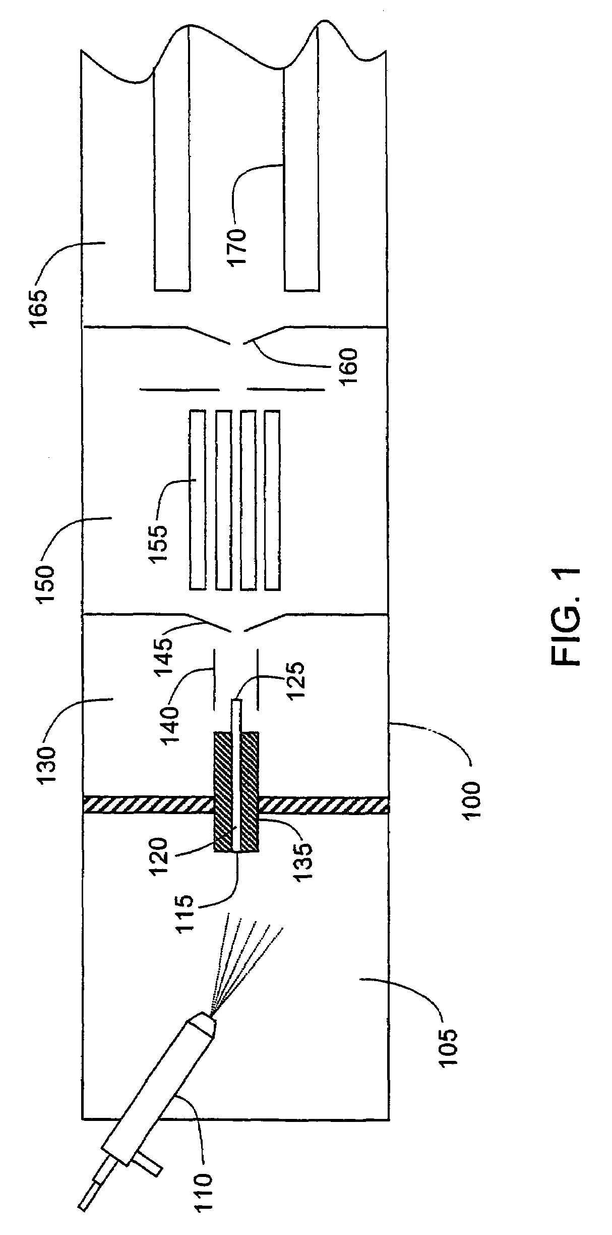
[0018]FIG. 1 i...


PUM


Abstract

An electrospray interface for forming ions from a liquid sample in a mass analyzing system includes a capillary tube having a free end for introducing a spray of droplets into an ionization chamber, a first gas passageway positioned near the capillary tube for directing a first gas stream into the ionization chamber, and a second gas passageway positioned more remotely from the capillary tube for directing a second, low-velocity gas stream into the ionization chamber. The second gas stream is heated to increase the droplet desolvation rate. A heated sampling capillary having an end extending into the ionization chamber guides the analyte ions toward a mass analyzer and evaporates the solvent from any incompletely desolvated droplets entering the sampling capillary.

Description

CROSS-REFERENCE TO RELATED APPLICATIONS[0001]This application claims the benefit of Provisional Application No. 60 / 573,225 filed May 21, 2004, which is incorporated by reference herein.BACKGROUND OF THE INVENTION[0002]1. Field of the Invention[0003]The invention relates generally to ion sources for mass analyzer systems, and more particularly to an electrospray interface.[0004]2. Description of the Prior Art[0005]In its basic form, the electrospray process consists of flowing a solution of the analyte through a capillary tube which is maintained at a high electrical potential with respect to a nearby surface. The solution emerges from a free end of the capillary tube and is dispersed into a fine mist of electrically charged droplets by the potential gradient at the tip of the capillary tube. The size of the droplets formed is determined by a combination of factors including, but not limited to, the solution flow rate, the applied potential and the properties of the solvent. Nebuliza...

Claims


Application Information

Patent Timeline
Patent Type & Authority Patents(United States)
IPC IPC(8): H01J49/44B65D39/00B65G59/00H01J49/04
CPCH01J49/04H01J49/167
Inventor THAKUR, ROHAN A.
Owner THERMO FINNIGAN
Why Eureka
Try Eureka