Diffraction grating device and optical apparatus

a technology of grating device and optical apparatus, which is applied in the direction of optical instruments, wavelength-division multiplex systems, instruments, etc., can solve the problems of inevitably divergence of diffracted light beams, complex and time-consuming process for the production of such films, and high cost, so as to achieve easy reduction of light beam divergence, high diffraction efficiency, and high diffraction efficiency

Inactive Publication Date: 2007-04-03
KONICA MINOLTA INC
View PDF3 Cites 1 Cited by
  • Summary
  • Abstract
  • Description
  • Claims
  • Application Information

AI Technical Summary

Benefits of technology

[0015]An object of the present invention is to solve the various problems described above that are experienced with a diffraction grating device that is designed to diffract light of different wavelengths. More specifically, a first object of the present invention is to provide a diffraction grating device for splitting or coupling light beams that permits the divergence of the light beams to be minimized easily, to provide a diffraction grating device that offers high diffraction efficiency while simultaneously offering a great angle difference between the incident and diffracted light beams, and to provide a diffraction grating device that offers high diffraction efficiency regardless of the polarization direction of the incident light.
[0016]Another object of the present invention is to provide a high-performance optical apparatus that splits or couples a plurality of light beams having different wavelengths. More specifically, a second object of the present invention is to provide an optical apparatus that can minimize the loss of light, to provide an optical apparatus that permits easy arrangement of a component for supplying a light beam and a component for receiving the light beam, and to provide an optical apparatus that can minimize the lowering of the intensity of light.

Problems solved by technology

A multiple-layer film, however, has the disadvantages of requiring a complicated and time-consuming process for the production thereof and being expensive.
Moreover, since the light that is made incident on the diffraction grating to be diffracted thereby is spread within a certain width of wavelengths, even when a parallel light beam is made incident on the diffraction grating, the diffracted light beam inevitably becomes divergent.
In an apparatus for optical communication, if the diffracted light beam is divergent, part of the light to be transmitted may fail to enter the optical transport member, or part of the light emerging from the optical transport member may fail to enter the light receiver.
This results in lower correctness in the signals transmitted and received.
This, however, has the disadvantage of making the apparatus larger.
In an optical recording / reproducing apparatus, if the diffracted light beam is divergent, the light cannot be converged in a very small area on a recording medium, resulting in a lower recording density, or part of the light reflected from the recording medium may fail to enter the light receiver, resulting in lower reading accuracy.
This, however, has the disadvantages of making the apparatus larger and lowering the response speed of the objective lens and thus the processing speed of the apparatus.
However, in an optical apparatus for optical communication, adopting the Littrow arrangement requires the optical transport member and the light receiver to be arranged spatially close together, making their arrangement difficult.
In optical communication, it is customary to use linearly polarized light to transport signals, and therefore failing to take into consideration the polarization direction of light with respect to a diffraction grating results in lower intensity of the transmitted and received light, leading to lower correctness in the signals transmitted and received.

Method used


Image

  • Diffraction grating device and optical apparatus
  • Diffraction grating device and optical apparatus
  • Diffraction grating device and optical apparatus

Examples


first embodiment

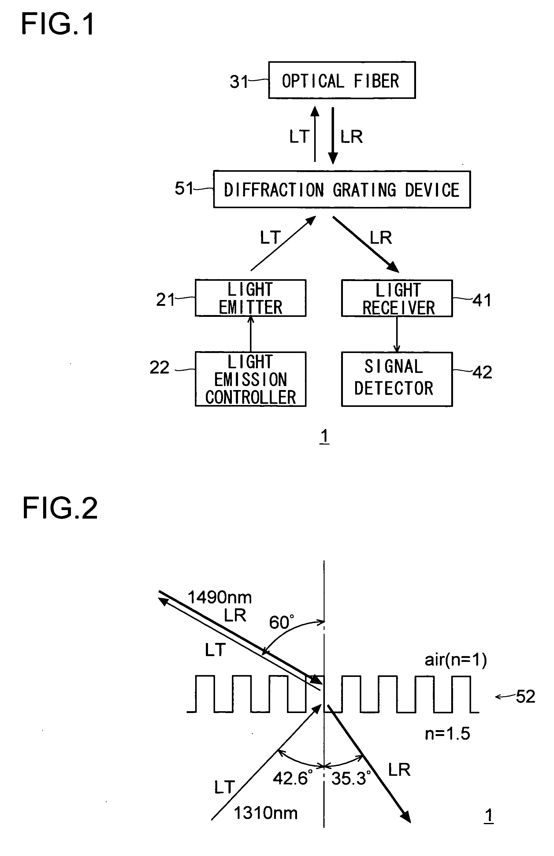
[0121]FIG. 1 schematically shows the construction of the optical apparatus 1 of a first embodiment of the invention. The optical apparatus 1 is a transmitter / receiver apparatus for use in optical communication, and includes a light emitter 21, a light emission controller 22, an optical fiber 31, a light receiver 41, a signal detector 42, and a diffraction grating device 51.

[0122]The light emitter 21 emits a light beam LT to be transmitted. The light emission controller 22 controls the light emission by the light emitter 21 so as to make the light beam LT emitted by the light emitter 21 carry a signal to be transmitted. The light emitter 21 includes, though not illustrated, a laser diode and a condenser lens so as to emit a parallel light beam obtained by condensing with the condenser lens the light emitted by the laser diode.

[0123]The optical fiber 31 transmits to the outside the light beam LT, carrying the signal to be transmitted, from the light emitter 21. The optical fiber 31 al...

second embodiment

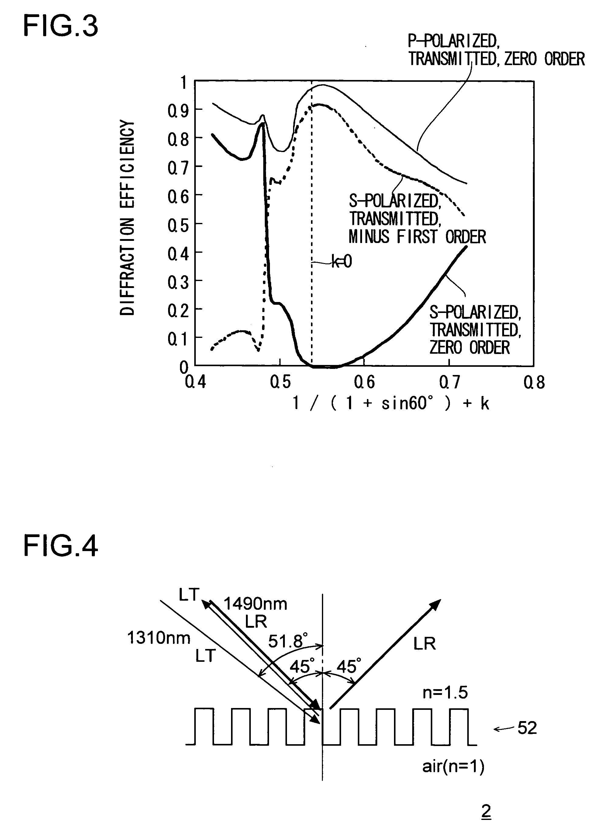
[0134]The optical apparatus 2 of this embodiment, too, is for use in optical communication, and has a construction similar to that of the optical apparatus 1 shown in FIG. 1. Specifically, the optical apparatus 2 includes a light emitter 21, a light emission controller 22, an optical fiber 31, a light receiver 41, a signal detector 42, and a diffraction grating device 51.

[0135]Now, the design of the diffraction grating 52 formed on the diffraction grating device 51 in the optical apparatus 2 will be described. Here, as in the first embodiment, it is assumed that the period of the elevations and depressions of the diffraction grating 52 is Λ; that the height difference between the elevations and depressions of the diffraction grating 52 is h; that, of the two media between which the diffraction grating 52 is sandwiched, the one present on the side thereof on which the light beam LT is incident has a refractive index of n1 and the other has a refractive index of n2; that the incidence...

third embodiment

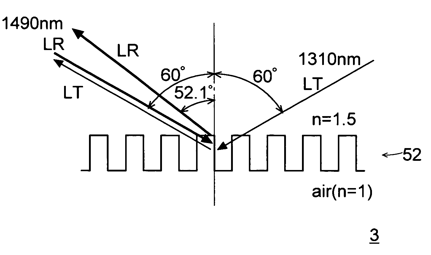
[0143]The optical apparatus 3 of this embodiment, too, is for use in optical communication, and has a construction similar to that of the optical apparatus 1 shown in FIG. 1. Specifically, the optical apparatus 3 includes a light emitter 21, a light emission controller 22, an optical fiber 31, a light receiver 41, a signal detector 42, and a diffraction grating device 51.

[0144]Now, the design of the diffraction grating 52 formed on the diffraction grating device 51 in the optical apparatus 3 will be described. Here, as in the first embodiment, it is assumed that the period of the elevations and depressions of the diffraction grating 52 is Λ; that the height difference between the elevations and depressions of the diffraction grating 52 is h; that, of the two media between which the diffraction grating 52 is sandwiched, the one present on the side thereof on which the light beam LT is incident has a refractive index of n1 and the other has a refractive index of n2; that the incidence...


PUM


Abstract

A diffraction grating device for splitting or coupling light beams permits the divergence of the light beams to be minimized easily. A first light beam is incident on a diffraction grating from the side thereof facing the inside of the device, and a second light beam is incident on the diffraction grating from the side thereof facing air. The diffraction grating transmits the first light beam by diffraction of the minus first order so that it travels in the reverse direction along the optical path of the second light beam before incidence, and transmits the second light beam by diffraction of the zero order. The second light beam, transmitted by diffraction of the zero order, spreads over a certain width of wavelengths, but does not diverge even after diffraction.

Description

[0001]This application is based on Japanese Patent Applications Nos. 2004-342485, 2004-342504, and 2004-342526 filed on Nov. 26, 2004, the contents of which are hereby incorporated by reference.BACKGROUND OF THE INVENTION[0002]1. Field of the Invention[0003]The present invention relates to a diffraction grating device designed to diffract light of different wavelengths, and to an optical apparatus that transmits and receives light of different wavelengths.[0004]2. Description of Related Art[0005]In optical communication, optical transport members such as optical fibers are used to achieve bi-directional transport of light of different wavelengths. In an optical apparatus used to transmit and receive light to perform such optical communication, i.e., in an optical apparatus that, on one hand, makes light carry signals and then transmits the light to an optical transport member and that, on the other hand, receives light from the optical transport member and then detects the signal ca...

Claims


Application Information

Patent Timeline
Patent Type & Authority Patents(United States)
IPC IPC(8): G02B5/18H04J14/02
CPCG02B5/1809G02B27/4261G02B27/4238G02B5/1861
Inventor OHMORI, SHIGETOSEKINE, KOUJIROUYOKOYAMA, MITSURU
Owner KONICA MINOLTA INC
Why Eureka
Try Eureka