
Cleaning system, device and method

a cleaning system and polymer material technology, applied in the direction of cleaning process and apparatus, measurement device, instruments, etc., can solve the problems of increasing the cost of final products sold, reducing the quality of electrical circuits, and reducing the cleaning efficiency of working surfaces of polymer materials, so as to achieve the effect of improving the cleaning efficiency of working surfaces

Inactive Publication Date: 2007-04-10
INT TEST SOLUTIONS LLC
View PDF16 Cites 32 Cited by
  • Summary
  • Abstract
  • Description
  • Claims
  • Application Information

AI Technical Summary

Benefits of technology

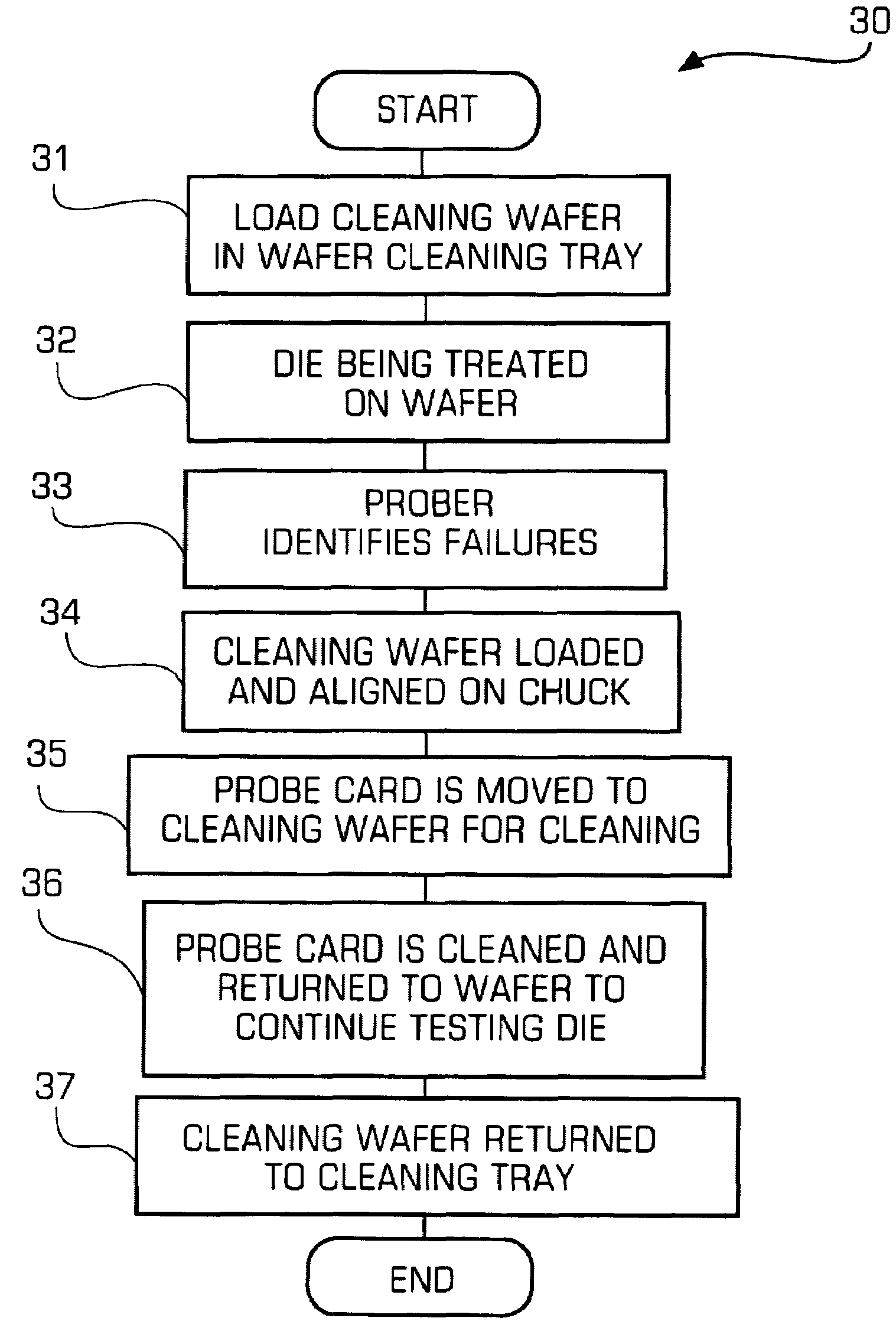
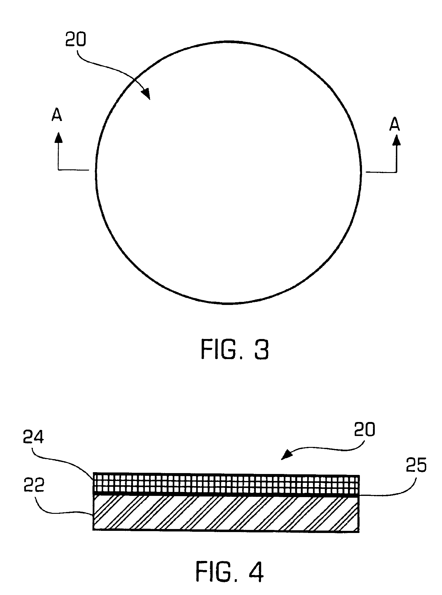
"The invention provides a cleaning medium for cleaning probe cards without removing them from the prober. The cleaning medium is placed within the prober and includes a substrate that matches the shape of a semiconductor wafer. The substrate has predetermined mechanical and chemical properties that clean the probe tips and remove debris and contaminants. The cleaning medium can be shaped or reshaped the probe elements during probing. The invention also provides a method for maintaining or modifying the shape of the probe elements by loading the cleaning medium into the prober or analyzer. The pad has a predetermined surface finish that can be detected by the prober or analyzer, and the surface texture contributes to the cleaning efficiency. The cleaning medium can automatically clean the probe tips and return to testing operations."

Problems solved by technology

The probe tips need to be cleaned to remove debris from them since the debris reduces the quality of the electrical circuit completed by the contact of the probe tips to any surfaces on a die.
The degradation of the quality of the electrical circuit caused by the probe tip debris may be interpreted by the test apparatus as a failure of the die under test even though the die is functioning correctly.
This false failure of the die results in the rejection or the rework of good die thereby increasing the cost of the final products sold.
Therefore, with thousands of probers operating worldwide, the impact to the industry from maintaining clean probes during testing can be very substantial.
However, in practice, physical defects in the wafer material and defects in the manufacturing processes invariably cause some of the individual devices to be non-functional, some of which may be repairable.
In particular, some product is actually repairable when the flaws are caught at the wafer lever.
Other product may not be repairable but may be used in a downgraded application from the original product.
This determination of the product's capabilities (a product definition provided by electrical probe testing) at the wafer level saves the manufacturer considerable cost later in the manufacturing process.
Although the scrubbing action improves the electrical contact between the probe tip and the bonding pad, it unfortunately also generates some debris (the scraped up oxide or other debris) that may also prevent the probe tip from making a good electrical contact with the bonding pad.
The probe tip may become contaminated with contaminates such as aluminum, copper, lead, tin, gold, bi-products, organic films or oxides resulting from the wafer and semiconductor device manufacturing and testing processes.
Typically, the debris generated by probing needs to be periodically removed from the probe elements to prevent a build-up which causes increased contact resistance, continuity failures and false test indications, which in turn results in artificially lower yields and subsequent increased product costs.
Also, some operators may clean the probe several times during the initial setup of the test equipment.
The process of cleaning in the prober using an abrasive pad burnishes the tips but it does not remove the debris.
The burnishing actually causes wear to the probe card by shortening the probe tips.
In addition, since it does not remove the debris, and since the debris exhibits a slight electrical charge, it attracts more debris so the probe card will require cleaning more often than the original clean card.
However, the brush operation tends to provide inconsistent cleaning and debris removal.
The brush operation has the potential to damage the planarity and alignment of the probes and may push contaminants into the array of the probes or up into the probe guide-plates.
Furthermore, some of the particulates during this operation may not be captured within the body of the brush and can become air-borne.
This is of particular concern when these particulates are environmentally hazardous.
When probe cards which have collected lead and tin are burnished, particulates of lead are released into the air that cause environmental hazards.
In addition, the acid solution requires a separate, rather expensive machine that sprays the solution onto the tips in a closed chamber.
These typical cleaning processes are expensive since the tester will have down time and a replacement card must be purchased to run while the other probe card is being cleaned.
In addition, the equipment and manual labor adds additional costs to the task performed.

Method used


Image

  • Cleaning system, device and method
  • Cleaning system, device and method
  • Cleaning system, device and method

Examples


Embodiment Construction

[0026]The invention is particularly applicable to a cleaning medium for cleaning the probes in a prober and it is in this context that the invention will be described. It will be appreciated, however, that the device and method in accordance with the invention has greater utility, such as cleaning other types of semiconductor processing equipment. The cleaning method can also be used on an analyzer which is a metrology tool used in the routine maintenance of probe cards.

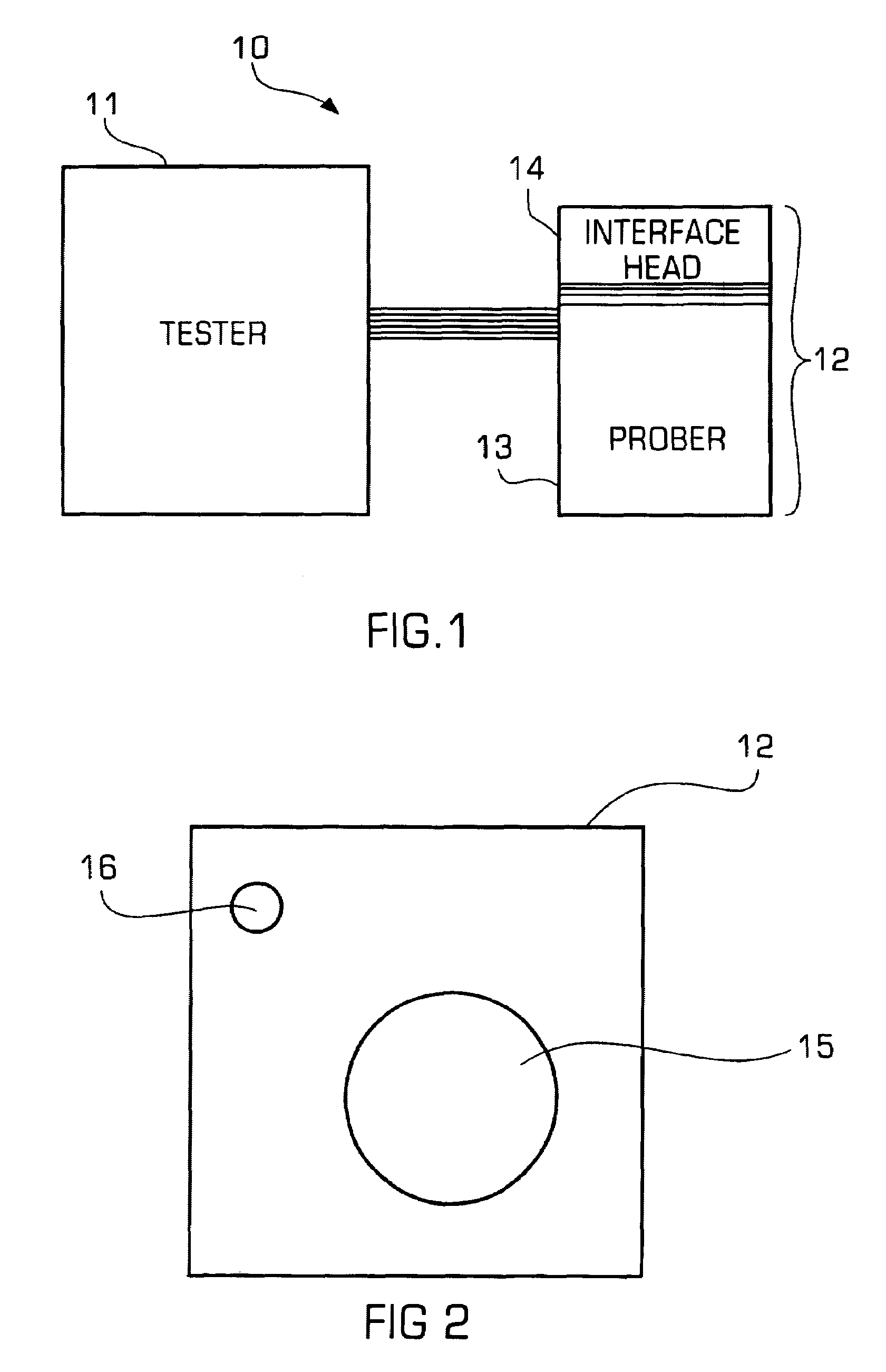
[0027]FIGS. 1 and 2 are diagrams illustrating a testing system 10 that may be cleaned using the cleaning medium in accordance with the invention. In particular, the system 10 may include a tester 11 electrically connected to a prober machine 12 that may actually apply the probes to the semiconductor wafer or die and test them. The prober machine 12 may further include a prober 13 and an interface head 14 as shown in FIG. 1. The prober machine 12 may also have an abrasion / sanding disk 16, which is typically used to bu...


PUM


Abstract

The cleaning device may clean probe elements. The probe elements may be the probe elements of a probe card testing apparatus for testing semiconductor wafers or semiconductor dies on a semiconductor wafer or the probe elements of a handling / testing apparatus for testing the leads of a packaged integrated circuit. During the cleaning of the probe elements, the probe card or the handler / tester is cleaned during the normal operation of the testing machine without removing the probe card from the prober. The cleaning device has a working surface with a particular characteristic (a matte finish or a conductive material) so that a prober is capable of automatically determining the location of the working surface of the cleaning device and therefore operate in an automatic cleaning mode.

Description

RELATED CASES / PRIORITY CLAIM[0001]This application is a continuation in part and claims priority under 35 USC 120 to U.S. patent application Ser. No. 09 / 624,750, filed on Jul. 24, 2000 now U.S. Pat. No. 6,777,966 and entitled “Cleaning System, Device and Method” which in turn claims priority under 35 USC 119(e) to U.S. Provisional Patent Application No. 60 / 146,526 filed Jul. 30, 1999. Both applications are incorporated herein by reference.BACKGROUND OF THE INVENTION[0002]This invention relates generally to a medium for cleaning a manual test interface while it is still in the prober. This manual interface is generally referred to as a probe card, which is used in the prober to make an electrical connection between the die on a silicon wafer and the tester so that the functionality of the die may be evaluated.[0003]Currently, the method for cleaning the probe card is to remove it from the prober and manually clean the debris from the probe tips. The probe tips need to be cleaned to r...

Claims


Application Information

Patent Timeline
Patent Type & Authority Patents(United States)
IPC IPC(8): G01R31/02B08B1/00G01R31/28
CPCB08B1/00G01R31/2831G01R31/2886B08B2220/01B08B1/14B08B1/10
Inventor HUMPHREY, GENEBROZ, JERRYADAMS, JOYCE
Owner INT TEST SOLUTIONS LLC
Learn More