Apparatus for automatically changing a robot tool tip member

a technology of automatic change and tool tip, which is applied in the direction of manufacturing tools, weld torches cleaning, transportation and packaging, etc., can solve the problems of increasing the running cost, limiting the operation range of the wrist axis of the robot, and inability to maintain the tool tip member threadedly mounted or demounted on or from the tool body in most cases. , to achieve the effect of reducing the number of setup steps, reducing the number of running costs, and reducing the number of running

Active Publication Date: 2007-04-17
FANUC LTD
View PDF16 Cites 21 Cited by
  • Summary
  • Abstract
  • Description
  • Claims
  • Application Information

AI Technical Summary

Benefits of technology

[0012]Therefore, in order to solve the problems of the prior arts described above, it is an object of the invention to provide an apparatus for automatically changing a robot tool tip member, which does not require an additional driving power source for changing a tool tip member, which apparatus has a simple structure so that a setup of the apparatus requires fewer operation steps, and which apparatus is suitably used in a typical robot system for performing arc welding or laser machining.
[0014]In the apparatus described above, the controller can control the operation of the robot arm of said robot to move the tool body around the rotation axis while keeping the tool body in contact with the tool tip member held by the tip member holding means, thereby to rotate a rotating member about the rotation axis while bringing about the relative rotation between the tool body and the tool tip member so as to demount or mount the tool tip member from or on the tool body.
[0016]Preferably, the rotation locking member includes a cylindrical portion formed with a receiving hole for receiving the tool tip member, so that the tool tip member is demounted or mounted from or on the tool body while the tool tip member is being inserted into the receiving hole. More preferably, a cylindrical outer tool tip member is further attached to the tool body so as to encircle the periphery of the tool tip member with a gap, and an outer diameter of the cylindrical portion of the rotation locking member is smaller than an inner diameter of the outer tool tip member, so that the inner tool tip member disposed inside said outer tool tip member can be changed while the outer tool tip member being mounted on the tool body.
[0018]In this case, it is preferable that the tool cleaning means includes a cylindrical element and the controller controls the operation of the robot arm to move the tool body around the rotation axis with the cylindrical element inserted between the inner tool tip member and the outer tool tip member, thereby to bring about relative rotation between the cylindrical element of the tool cleaning means and the inner and outer tool tip members so as to clean both or either one of the inner tool tip member and the outer tool tip member.
[0020]Thus, according to the present invention, as the tool tip member changing jig is utilized, it is not necessary to provide another driving power sources besides the robot mechanism, so that additional running costs are not required. Further, as all that is required, for addition of the tool tip member changing function, is a provision of a tool tip member changing jig and cumbersome wiring / tubing works are not needed, the addition of the function requires minimum setup steps. Moreover, if the tool tip member changing jig is used when the tool tip member is changed, the wrist axis of the robot does not need to rotate continuously. Therefore, the present invention can also be applied to a case in which lines for assist gas and the like are connected to the tool body. Thus, according to the present invention, the operation for changing the tool tip member can be implemented easily by using a robot that is used in a typical robot system for arc welding and laser machining.

Problems solved by technology

However, when a dedicated automatic changing apparatus for demounting or mounting a tool tip member is used in the method described above, the automatic changing apparatus requires a driving power source to drive actuators used for fastening the tool tip member, resulting in a problem that running costs are increased.
However, in a typical robot system for performing arc welding or laser machining, as the robot itself has various lines (wirings, tubings and pipings) attached thereto, such as a motor control line, an energy supply line for a tool body, a sensor signal line, an assist gas supply line and the like, the operation range of the wrist axis of the robot is restricted by these lines and, therefore, the continuous rotation required for threadedly mounting or demounting the tool tip member on or from the tool body is not permitted in most cases.
For example, regarding the line for supplying assist gas to the machining head, it is apparent that the line arrangement wherein the lines are attached to the outside of the apparatus is incompatible with the requirement of continuous rotation described above.

Method used


Image

  • Apparatus for automatically changing a robot tool tip member
  • Apparatus for automatically changing a robot tool tip member
  • Apparatus for automatically changing a robot tool tip member

Examples


Embodiment Construction

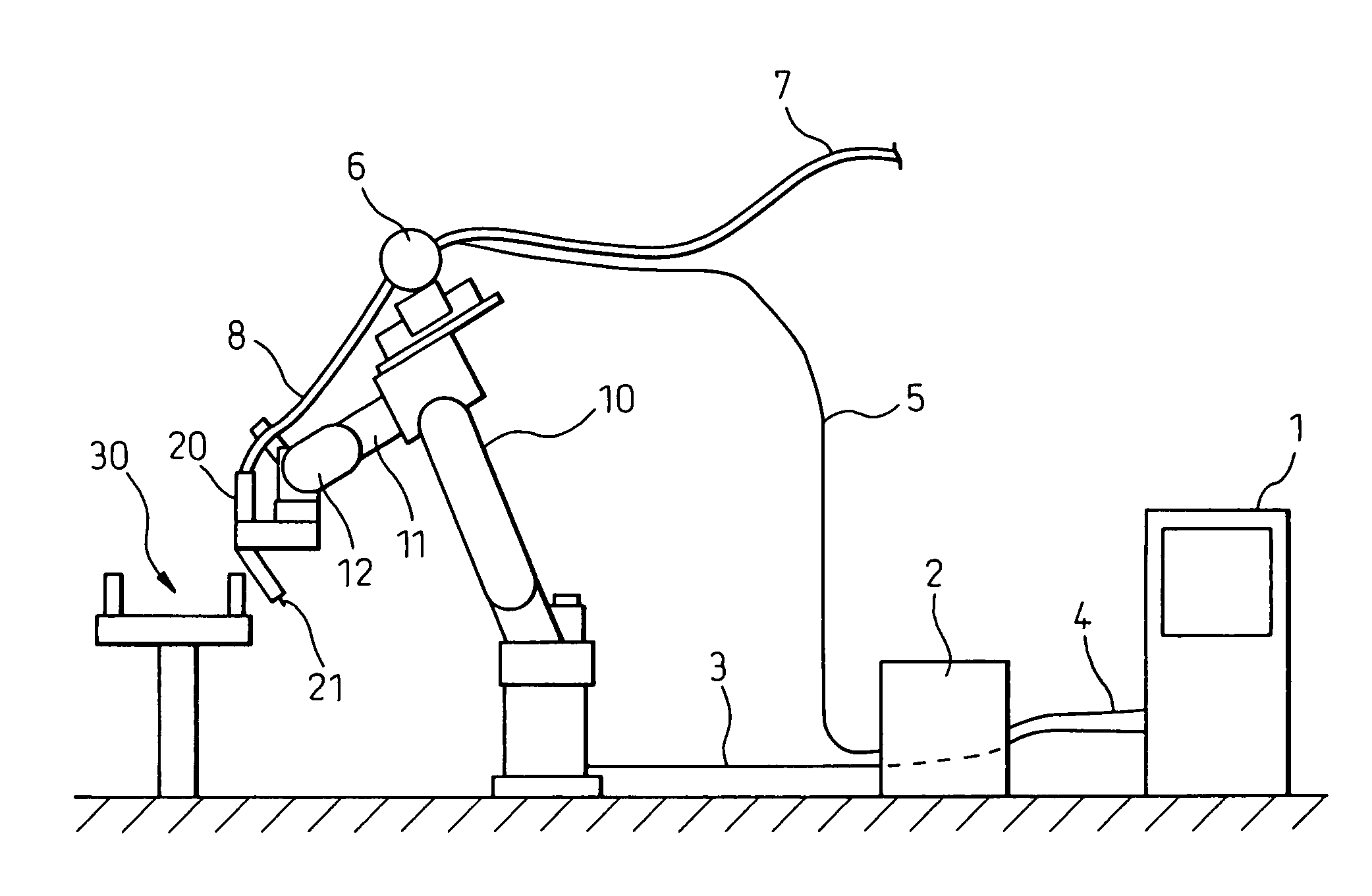
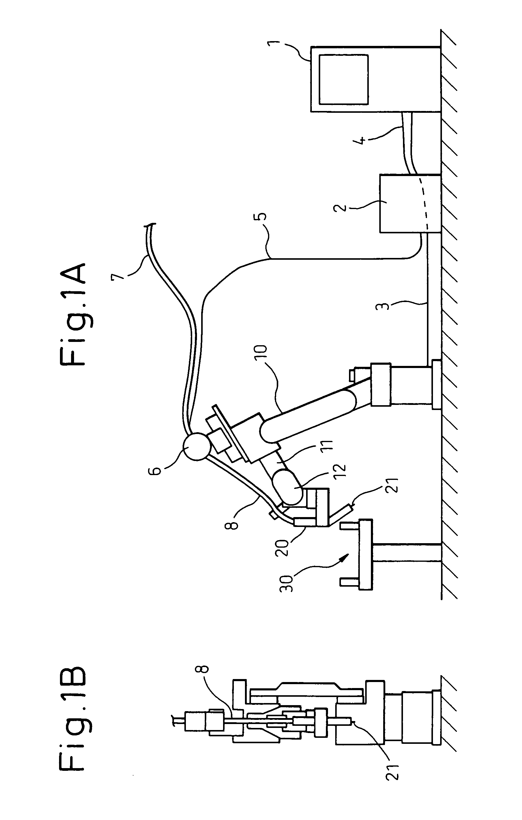
[0033]FIGS. 1A and 1B schematically show an entire configuration of an embodiment of a system to which the present invention is applied. As is apparent from the figures, this system utilizes an arc welding robot and includes a robot controller 1 for functioning as a control section of the system, a welding power source 2, a wire feeding device 6, a welding wire 7, a torch cable 8, a robot mechanism 10 having a robot arm, and a welding torch (or a tool body) 20. A robot control cable 3 connects between the robot controller 1 and the robot mechanism 10, and a welding power source control cable 4 connects between the robot controller 1 and the welding power source 2. It should be noted that FIG. 1A illustrates that the robot control cable 3 runs behind the welding power source 2.

[0034]The welding torch 20 is mounted on a wrist element 12 of the robot mechanism 10. The welding wire 7 is fed from a welding wire drum (not shown) to the welding torch 20 through the wire feeding device 6 pl...


PUM

PropertyMeasurementUnit
areaaaaaaaaaaa
relative rotationaaaaaaaaaa
torqueaaaaaaaaaa

Abstract

An apparatus for automatically changing a tool tip member for a robot includes a tip member changing jig disposed in an operational area of the robot. The tip member changing jig includes a base member, a rotating member supported by the base member so as to be rotatable about a rotation axis, and tip member holding means disposed at positions that are offset from the rotation axis of the rotating member. The tip member holding means holds the tool tip member so that a central axis of relative rotation, for threadedly mounting or demounting the tool tip member on or from the tool body, extends substantially parallel to the rotation axis of the rotating member and so that rotation of the tool tip member, with respect to the rotating member, is locked.

Description

CROSS-REFERENCE TO RELATED APPLICATIONS[0001]This application is as divisional application of U.S. application Ser. No. 10 / 784,158, filed on Feb. 24, 2004, now pending, and also claims priority to Japanese Application No. 2003-047995, filed Feb. 25, 2003, the disclosure of which is incorporated herein by reference.BACKGROUND OF THE INVENTION[0002]1. Field of the Invention[0003]The present invention relates to an apparatus for automatically changing a robot tool tip member, which operates in the condition that the tool tip member is threadedly mounted on a tool body which is, in turn, mounted on a robot arm. For example, the present invention is applied to an apparatus for automatically changing a tool tip member mounted on a distal end of a tool body for arc welding or laser machining.[0004]2. Description of the Related Art[0005]When an industrial robot (hereinafter simply referred to as a “robot”) is used for arc welding or laser machining, a tool tip member is mounted on a distal ...

Claims


Application Information

Patent Timeline
Patent Type & Authority Patents(United States)
IPC IPC(8): B23Q3/155B23K9/12B23K9/32B23K11/30B23K26/08B25J15/04
CPCB23K9/32B23K9/328B23K11/3072B23K26/0884B23K26/1482Y10T483/15Y10T483/17Y10T483/1873Y10T483/13
Inventor HAGIHARA, MASAHIROSAITO, MASAAKITSUMURA, TAKESHIINOUE, TOSHIHIKO
Owner FANUC LTD
Why Eureka
Try Eureka