Amplitude deviation correction circuit

a correction circuit and amplitude technology, applied in the field of amplitude deviation correction circuits, can solve the problems of difficult miniaturization of circuits, difficult to use large-scale integrated circuits, and difficulty in reducing the number of parts in the futur

Inactive Publication Date: 2007-04-17
NEC CORP
View PDF14 Cites 8 Cited by
  • Summary
  • Abstract
  • Description
  • Claims
  • Application Information

AI Technical Summary

Benefits of technology

[0018]It is an object of the present invention to provide an amplitude deviation correction circuit

Problems solved by technology

The receiver of the heterodyne system having the construction described above has a problem in that it is difficult to use a large scale integrated circuit to form the receiv

Method used


Image

  • Amplitude deviation correction circuit
  • Amplitude deviation correction circuit
  • Amplitude deviation correction circuit

Examples


Embodiment Construction

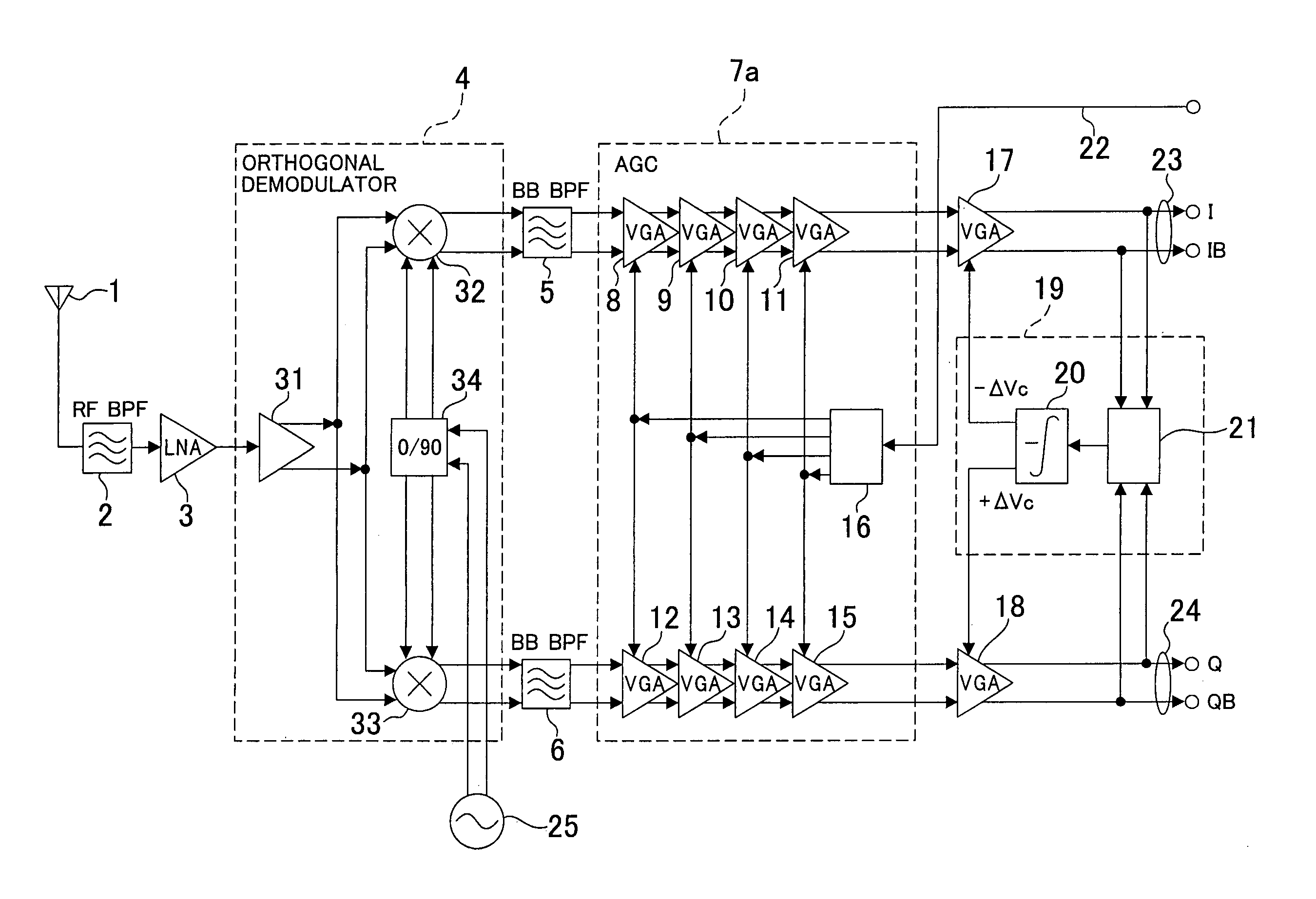
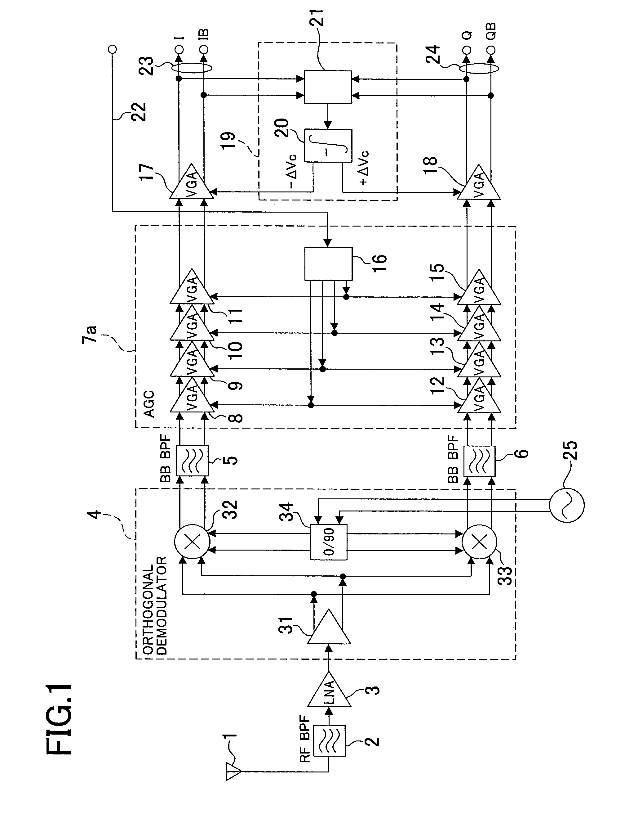
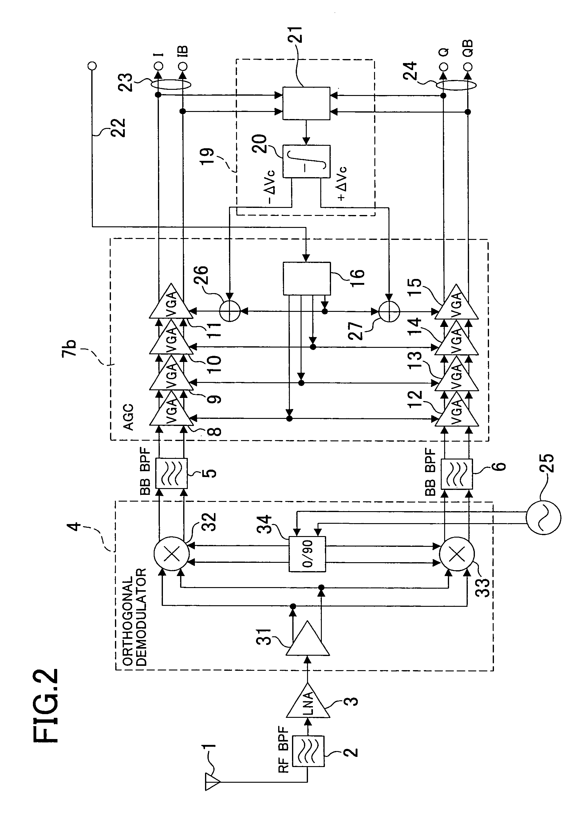
[0030]Referring to FIG. 1, there is shown an amplitude deviation correction circuit to which the present invention is applied. The amplitude deviation correction circuit is incorporated in a receiver of the direct conversion system which includes an antenna 1, a radio frequency band-pass filter 2, a low noise amplifier 3, an orthogonal demodulator 4 which includes an amplifier 31, a pair of double-balanced mixers 32 and 33, and a 90° phase branching unit 34, a pair of baseband filters 5 and 6, and an AGC circuit 7a which includes variable gain amplifiers 8 to 15 and a gain controlling voltage generation circuit 16. The elements of the receiver mentioned are all similar to those of the receiver of the direct conversion system described hereinabove with reference to FIG. 6, and therefore, overlapping description is omitted herein to avoid redundancy. The amplitude deviation correction circuit according to the present invention is positioned following the AGC circuit 7a.

[0031]The ampl...


PUM


Abstract

A novel amplitude deviation correction circuit which corrects an amplitude deviation between an I signal and a Q signal is disclosed. An average amplitude deviation between an I signal amplified by a variable gain amplifier and a Q signal amplified by another variable gain amplifier is detected by an amplitude comparison circuit, and +1 volt or −1 volt is outputted in response to a result of the detection. An integration circuit integrates the output of the amplitude comparison circuit and controls the gains of the variable gain amplifiers in response to a result of the integration.

Description

BACKGROUND OF THE INVENTION[0001]1. Field of the Invention[0002]The present invention relates to an amplitude deviation correction circuit, and more particularly to an amplitude deviation correction circuit which corrects an amplitude deviation between two baseband signals of an I signal and a Q signal after orthogonal demodulation in a receiver for an orthogonal phase modulation signal which employs a direct conversion system.[0003]2. Description of the Related Art[0004]Conventionally, orthogonal phase modulation is used for a digital portable telephone receiver (PDC (Personal Digital Cellular system), a PHS (Personal Handy phone System) receiver and a CDMA (Code Division Multiple Access) receiver. In the receivers mentioned, a heterodyne system is used most popularly wherein a received radio frequency signal is converted into an intermediate frequency signal and then two baseband signals are produced by an orthogonal demodulator, whereafter decoding is performed for the baseband s...

Claims


Application Information

Patent Timeline
IPC IPC(8): H04L25/06H03G3/20H04L27/22H03G3/30H04L27/38
CPCH03G3/3052H03G3/3078
Inventor ICHIHARA, MASAKI
Owner NEC CORP
Why Eureka
Try Eureka