Optical transfer system having a transmitter and a receiver

a technology of optical transfer system and receiver, which is applied in the field of data transfer system, can solve the problems of signal interference in the transmission and display of digital signals, cost increase with the use of analog-to-digital converters, and restrictions in the signal transfer distance, so as to achieve rapid transmission and eliminate electromagnetic interference between cables.

Inactive Publication Date: 2007-04-24
SAMSUNG ELECTRONICS CO LTD
View PDF11 Cites 17 Cited by
  • Summary
  • Abstract
  • Description
  • Claims
  • Application Information

AI Technical Summary

Benefits of technology

[0006]An object of the present invention is to provide an optical transfer system having a transmitter and a receiver, by which rapid transmission can be achieved, and by which electromagnetic interference between cables can be eliminated.
[0009]Yet another object of the present invention is to provide a data restoration and skew compensation circuit capable of stably restoring original information data by compensating for skew between data and a word clock signal which are received via a transmission channel from the receiver.

Problems solved by technology

However, this transmission and display of digital signals may be affected by signal interference or noise.
In this case, the cost may rise with the use of an analog-to-digital converter.
Furthermore, when data is transferred via a coaxial cable, restrictions in the signal transfer distance are evident.
That is, when the length of a cable increases, long-distance transmission can be difficult due to generation of noise due to the cable length.
Also, electromagnetic interference (EMI) can occur between cables, having an adverse effect on transmission quality.

Method used


Image

  • Optical transfer system having a transmitter and a receiver
  • Optical transfer system having a transmitter and a receiver
  • Optical transfer system having a transmitter and a receiver

Examples


Embodiment Construction

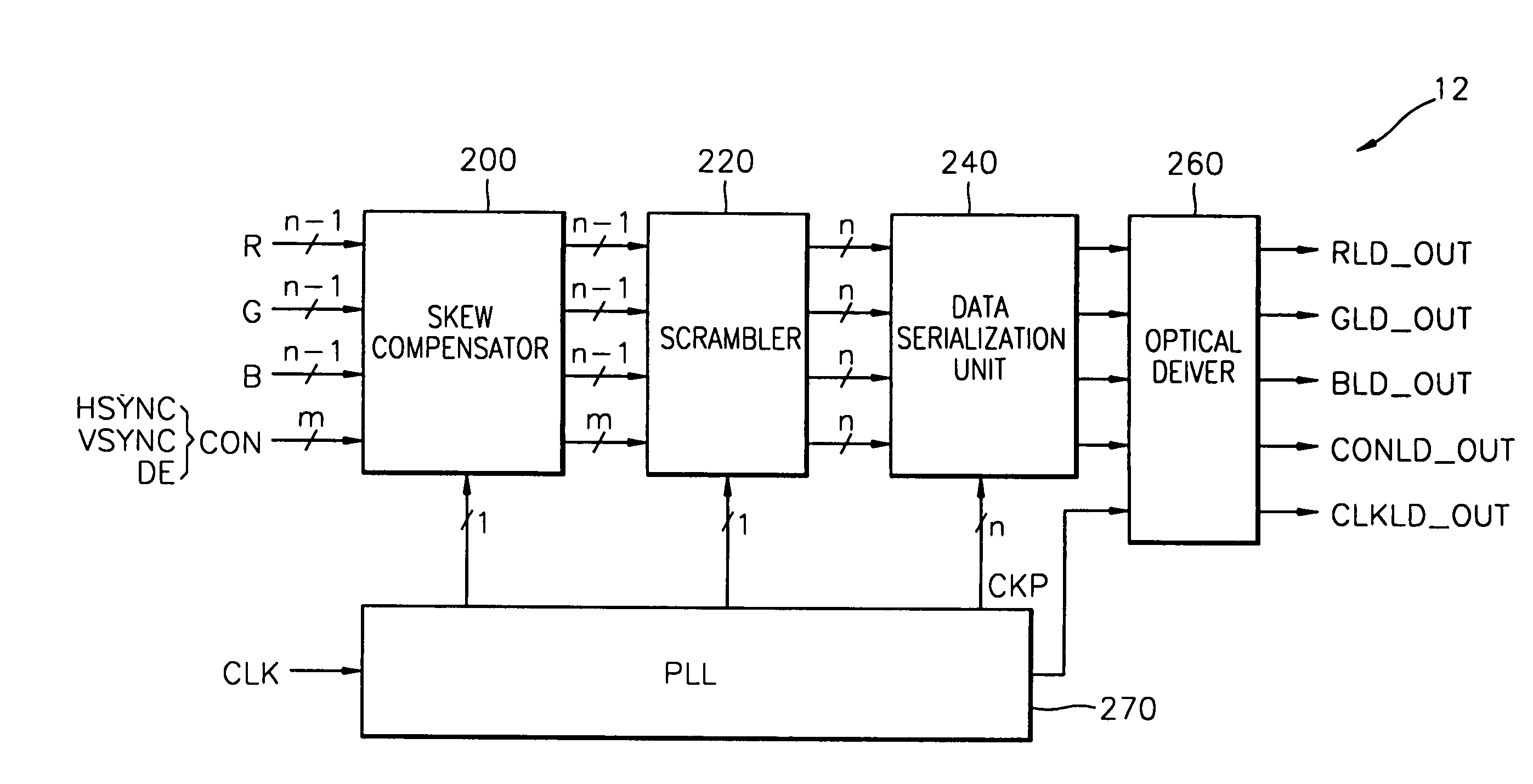
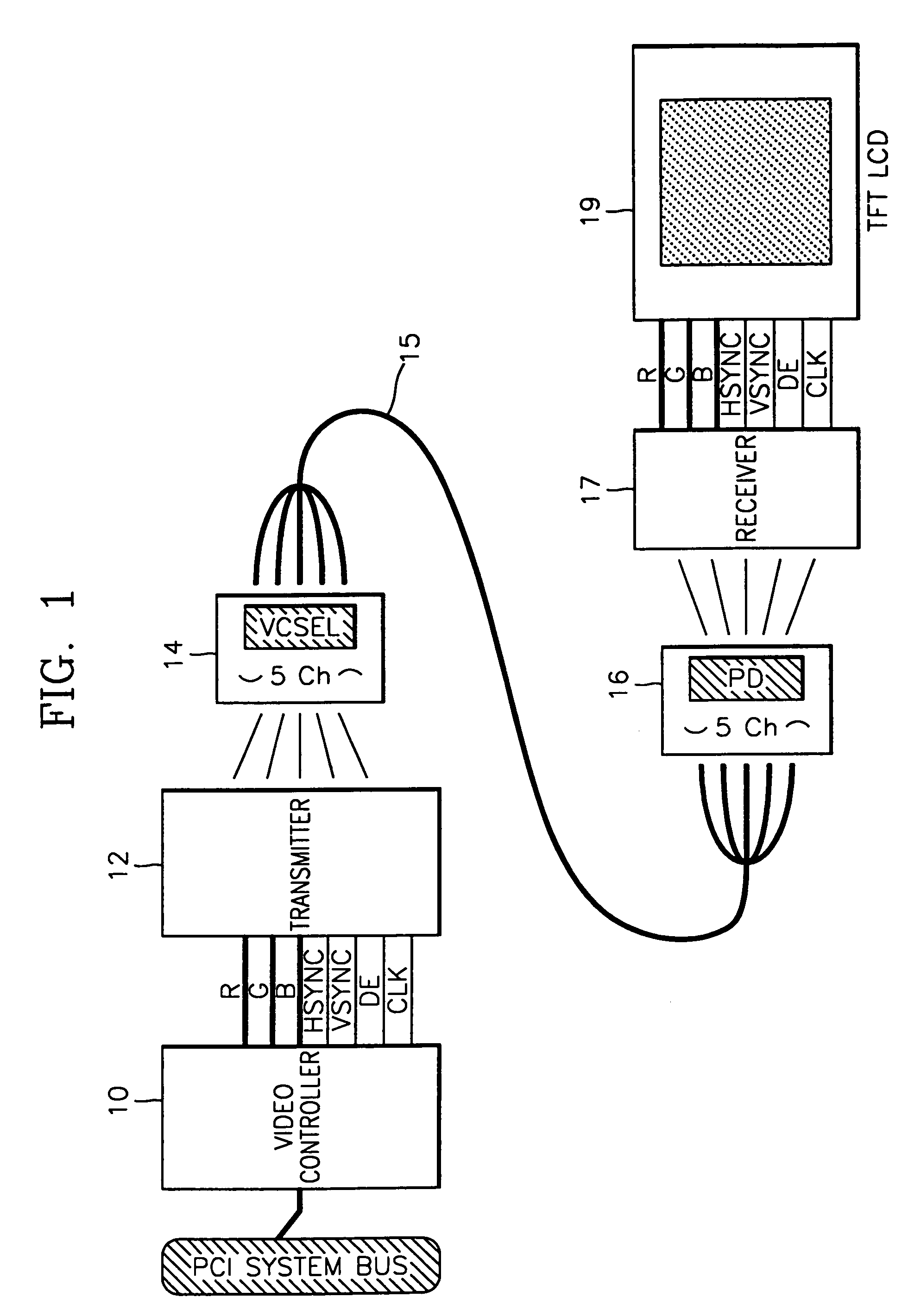
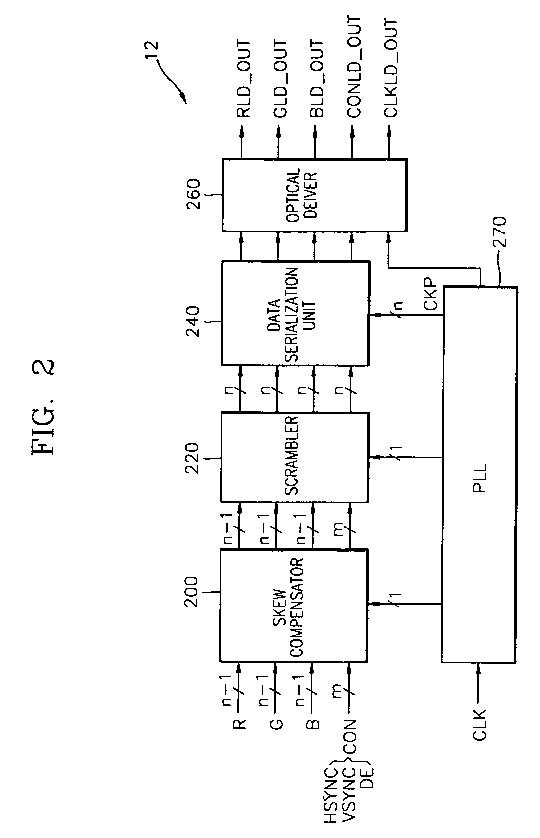
[0037]Referring to FIG. 1, an optical transfer system according to an embodiment of the present invention includes a video controller 10, a transmitter 12, an optical transmission diode 14, an optical fiber 15 (for example comprising plastic), an optical reception diode 16 and a receiver 17. For convenience of explanation, a thin film transistor (TFT) LCD panel 19 is shown in FIG. 1. The optical transfer system according to the present invention can be used between an LCD monitor and a personal computer (PC) or between other display devices and external apparatuses.

[0038]The video controller 10 separates a video signal received from a PC central processing unit main body, or from another external source, via a programmable communication system bus (for example, peripheral component interconnect (PCI) bus), into an R / G / B color signal and a horizontal / vertical synchronous signal HSYNC / VSYNC. Additionally, the video controller 10 transfers the R / G / B color signal or the horizontal / verti...


PUM


Abstract

An optical transfer system having a transmitter and a receiver converts an externally-applied video signal into an optical signal and restores the optical signal to the original video signal The system includes a video controller, a transmitter, a transmission photo diode, an optical transmission line, a reception photo diode, and a receiver. The video controller separates color signals and a horizontal / vertical synchronous signal from the video signal, and transmits the color signals and the horizontal / vertical synchronous signal in response to externally-applied predetermined data enable and clock signals. The transmitter skew-compensates and compresses signals received from the video controller and converts the compressed signals into a driving current. The transmission photo diode converts the driving current into an optical signal and outputs the optical signal. The optical transmission line is comprised of a predetermined number of channels, and transmits the optical signal. The reception photo diode converts the optical signal received from the optical transmission line into a current signal and outputs the current signal. The receiver converts the current signal into a voltage signal, decompresses the voltage signal, compensates for the skew of the voltage signal, and restores the original signal. Accordingly, data for an LCD monitor is optically transmitted, so that rapid data transmission can be achieved and so that electromagnetic interference (EMI) noise can be removed.

Description

BACKGROUND OF THE INVENTION[0001]1. Field of the Invention[0002]The present invention relates to data transfer systems, and more particularly, to an optical transfer system having a transmitter and a receiver.[0003]2. Description of the Related Art[0004]In general, conventional cathode ray tube (CRT) monitors are controlled using analog control systems. Contemporary liquid crystal display (LCD) monitors, however, use digital signals as driving signals. For example, an LCD monitor that is installed exterior to a computer processor, converts analog video signals into digital signals using an analog-to-digital converter within the monitor, and displays data on its screen in response to the digital signals. Also, LCD monitors for notebook computers receive digital signals from the main processor and display data corresponding to the received digital signals on their screens. However, this transmission and display of digital signals may be affected by signal interference or noise. To mit...

Claims


Application Information

Patent Timeline
Patent Type & Authority Patents(United States)
IPC IPC(8): H04N9/475
CPCH04N21/4122H04N21/4143H04N21/4363H04N21/4367
Inventor LEE, JAE-HUNMOON, BYUNG-JOON
Owner SAMSUNG ELECTRONICS CO LTD
Why Eureka
Try Eureka