Optical transmission system

a transmission system and optical transmission technology, applied in the field of optical transmission systems, can solve the problems of poor reliability of pump light sources, large non-linear effect, and inability to efficiently obtain raman gain, etc., and achieve the effects of low degradation, high raman gain efficiency, and small mode field diameter

Inactive Publication Date: 2007-04-24
FUJITSU LTD
View PDF10 Cites 5 Cited by
  • Summary
  • Abstract
  • Description
  • Claims
  • Application Information

AI Technical Summary

Benefits of technology

[0025]In the configuration described above, since the wavelength dispersion of each combined transmission line section is positive or negative and is not zero, there is little degradation due to cross-phase modulation of a transmission waveform. By properly locating a combined transmission line section with positive accumulated wavelength dispersion and a combined transmission line section with negative accumulated wavelength dispersion, the accumulated wavelength dispersion of the entire transmission line can be made substantially zero. Furthermore, pump light for Raman amplification is inputted to the second optical fiber with negative dispersion. Here, an optical fiber with negative dispersion usually has a small mode field diameter and high Raman gain efficiency, compared with an optical fiber with positive dispersion. Therefore, no special fiber (centralized Raman amplifier) is needed to obtain a desired gain.
[0026]In the system described above, the transmission line can also be constituted by repeating a basic pattern transmission line section compo...

Problems solved by technology

Although as described above, a method for managing the wavelength dispersion of a transmission line in order to reduce the influence of the non-linear effect is known, the conventional method has the following problems.
However, since usually a positive-dispersion fiber has a large mode field diameter, Raman gain cannot be efficiently obtained.
In other words, obtaining a prescribed gain using a positive-dispersion fiber requires extremely large pump power, and the extremely large pump power badly affects the reliability of an pump light source.
However, if an optical fiber with an extremely small mode field diameter is used, the non-linear effect becomes large and the transmission character...

Method used


Image

  • Optical transmission system
  • Optical transmission system
  • Optical transmission system

Examples


Embodiment Construction

[0052]The embodiments of the present invention are described below with reference to the drawings.

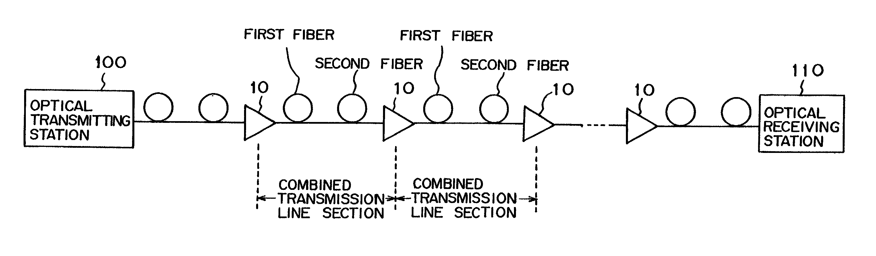
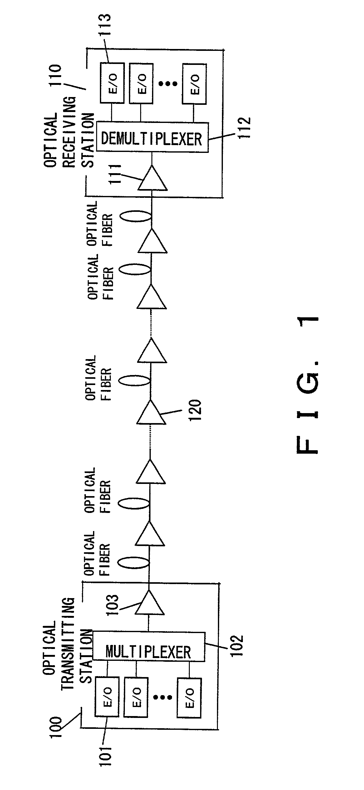
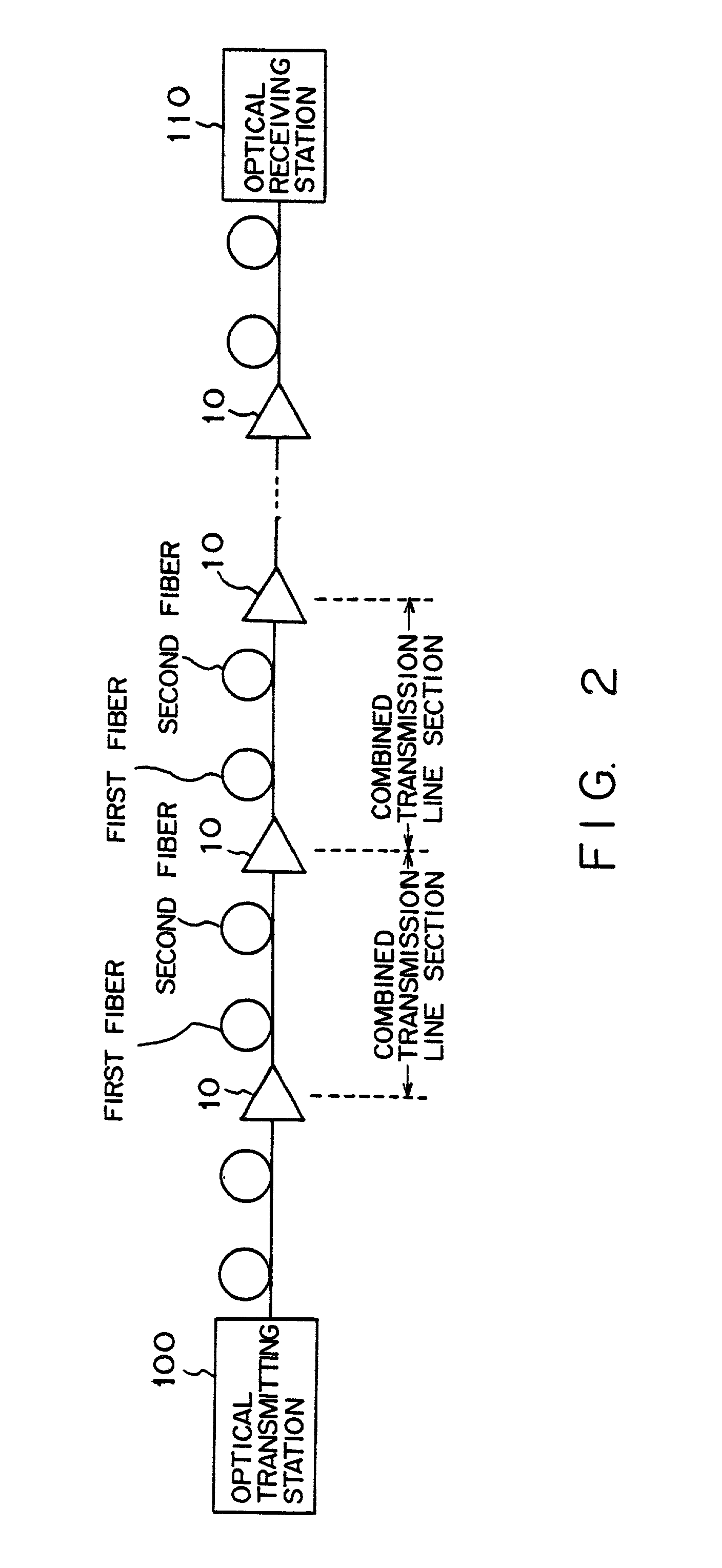
[0053]FIG. 2 shows the configuration of the optical transmission system in an embodiment of the present invention. The optical transmitting station 100 and optical receiving station 110 shown in FIG. 2 are basically the same as those shown in FIG. 1.

[0054]In a transmission line between the optical transmitting station 100 and optical receiving station 110, a plurality of optical repeaters 10 are provided. The plurality of optical repeaters 10 are basically located at equal intervals. Each optical repeater 10 has a function to generate pump light for Raman amplification utilizing the vibration of a molecule composing an optical fiber, which is a medium for transmitting signal light, and to supply the pump light to the transmission line.

[0055]Each of optical transmission lines between the optical transmitting station 100 and an optical repeater 10, between adjacent optical repeaters 10, a...


PUM


Abstract

A plurality of optical repeaters are provided on a transmission line between an optical transmitting station and an optical receiving station. A combined transmission line section is provided between optical repeaters. The combined transmission line section is composed of the first optical fiber, which is a positive-dispersion fiber, and the second optical fiber, which is a negative-dispersion fiber. Signal light is inputted to the first optical fiber in each combined transmission line section. Each optical repeater inputs pump light to the second optical fiber.

Description

BACKGROUND OF THE INVENTION[0001]1. Field of the Invention[0002]The present invention relates to an optical transmission system utilizing Raman amplification.[0003]2. Description of the Related Art[0004]Conventionally, in a long-haul optical transmission system, a plurality of repeaters (optical regenerating repeaters) were provided on a transmission line, and a 3R (retiming, reshaping and regenerating) process was performed to electrical signal converted from optical signal in each repeater. Then, the optical signals were generated from the electrical signals and were transmitted to the transmission line again. However, lately, both the performance and cost of an optical amplifier have been improved and reduced, respectively, and an optical transmission system using an optical amplifier as a linear repeater has been commercialized. Thus, by replacing an optical regenerating repeater with an optical amplifier repeater, the number of components of a repeater apparatus is greatly redu...

Claims


Application Information

Patent Timeline
IPC IPC(8): H04B10/08H04B10/00H04B10/12H04J14/02G02F1/35H01S3/06H01S3/067H01S3/30H04B10/2507H04B10/2513H04B10/2543H04B10/29H04B10/291H04J14/00
CPCH04B10/25253H04B10/2916
Inventor TANAKA, TOSHIKINAITO, TAKAO
Owner FUJITSU LTD
Why Eureka
Try Eureka