
Wavelength multiplex transmission device

a transmission device and wavelength technology, applied in the field of optical communication, can solve the problems of inefficient methods, deterioration of signal waveforms, and increase the effect of delay on waveform deterioration, so as to reduce initial costs, reduce the effect of delay, and save spa

Inactive Publication Date: 2007-04-24
NEC CORP
View PDF20 Cites 1 Cited by
  • Summary
  • Abstract
  • Description
  • Claims
  • Application Information

AI Technical Summary

Benefits of technology

[0015]Thus, an object of the present invention is to provide a wavelength multiplex transmission device which not only enables constant optical amplification characteristics to be maintained at the time of expansion while involving no in-service signal light error but also realizes suppression of initial costs and saving of space.
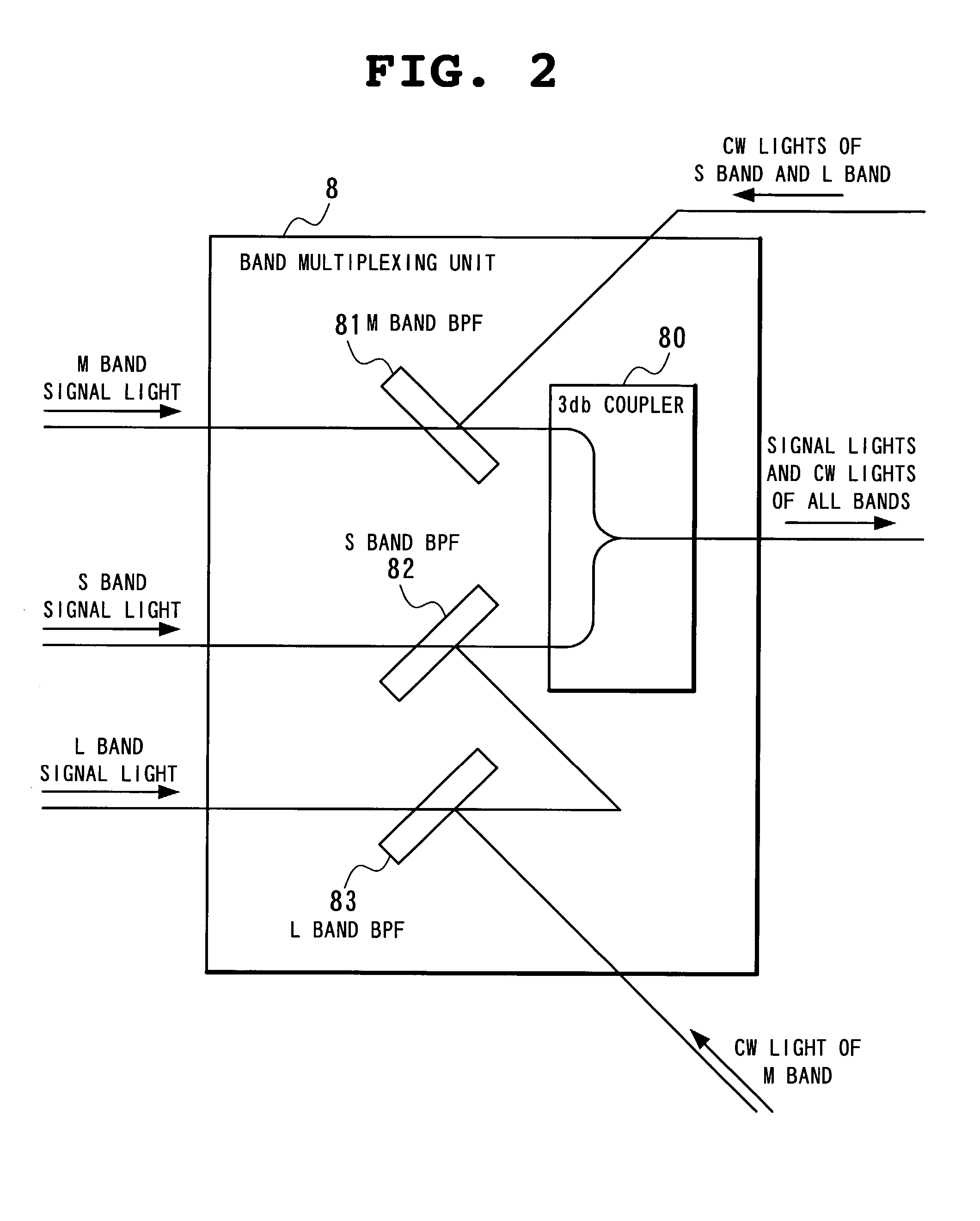
[0051]Then, the present invention produces the following effects because of adoption of such structure as described above. Since a CW light is applied through the band multiplexing unit, with respect to optical amplifiers succeeding the band multiplexing unit (total band optical amplifier and repeaters on a transmission path), constant amplifier operation can be maintained by supplementing signal light power as of before expansion with the CW light. As to components at a stage preceding to the band multiplexing unit, since only a path on which an introduced signal wavelength propagates should be ensured, a block band unit to which signal is yet to propagate and components preceding thereto can be omitted. Also as to input power of a band optical amplifier in a block dispersion compensating unit, it should be maintained at a fixed value regardless of the number of signal lights added, so that by reducing signal light power already expanded by as much power as input power of the band optical amplifier increased by the expansion of the signal light, the input power is maintained at a constant value.
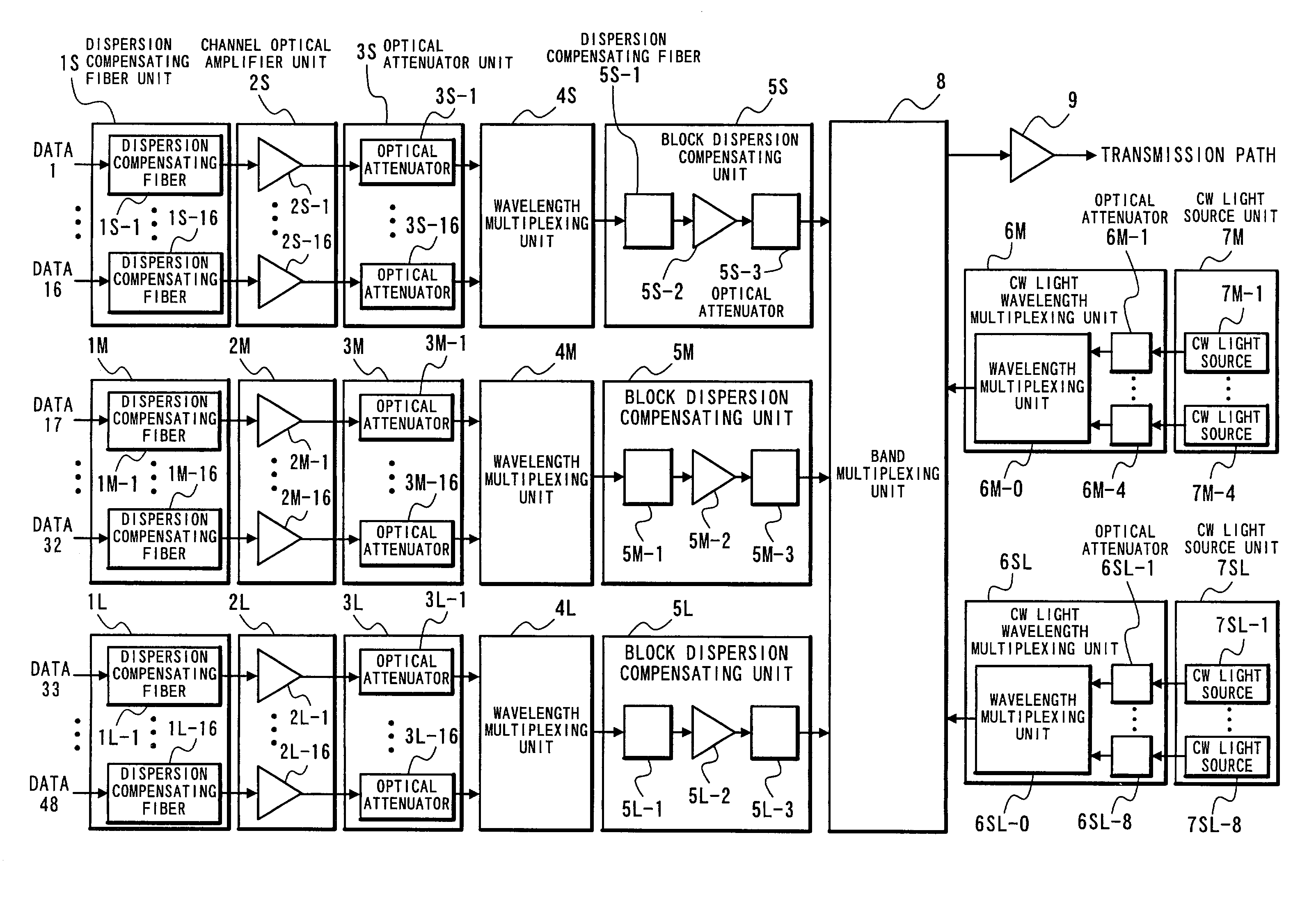
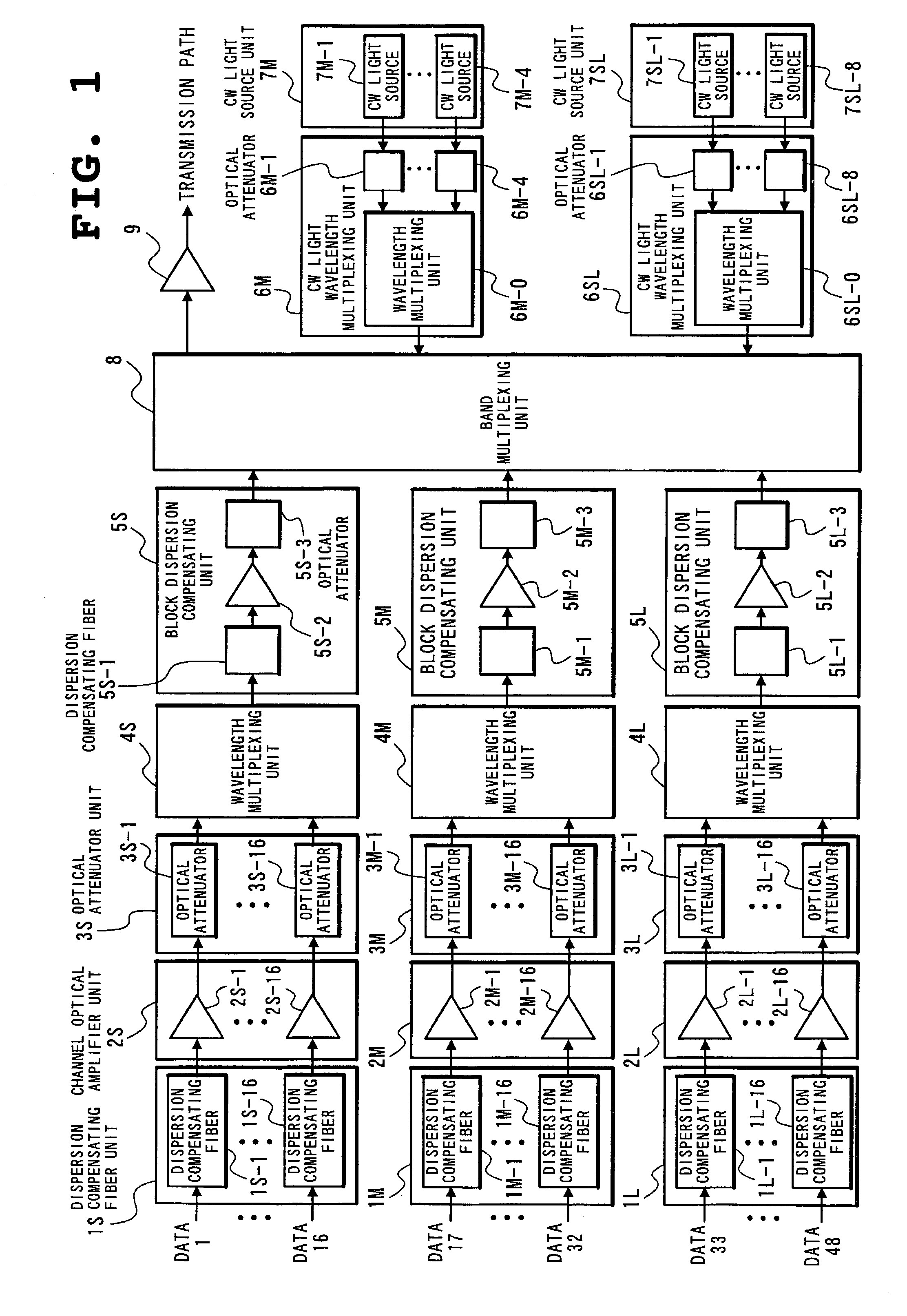
[0053]a) In order to suppress signal light waveform deterioration caused by the effect of dispersion in a transmission path by efficiently conducting dispersion compensation, the present invention includes a block band unit for dividing an entire signal band into an appropriate number of bands, a band multiplexing unit for multiplexing the divisional bands, a total band optical amplifier for amplifying all the multiplexed signal lights in the lump and transmitting the amplified signals to a transmission path to have predetermined power, and a CW light output unit for supplementing signal light power in preparation for future expansion. Then, by applying a CW light output from the CW light output unit to the band multiplexing unit, constant characteristics of the total band optical amplifier and repeaters on the transmission path can be maintained regardless of the number of signals added.
[0054]b) In the above-described a), the block band unit includes a dispersion compensating fiber unit whose compensation varies with a signal wavelength, a channel optical amplifier for compensating for a pass loss at the fiber unit and outputting the compensated signal light with higher power, an optical attenuator for adjusting level of each signal light power, a wavelength multiplexing unit for multiplexing signal lights in a band, a dispersion compensating fiber for uniformly and efficiently conducting dispersion compensation for a signal light in a block, a band optical amplifier for compensating for a pass loss at the fiber and an optical attenuator for uniformly varying a signal light level in the block. Then, with the use of only introduced signal light power, by making light power applied to the band optical amplifier be constant regardless of the number of signals introduced by means of the two kinds of optical attenuators, constant operation of the amplifiers can be maintained. In addition, channel power output to the band multiplexing unit remains unchanged.
[0055]c) In the above-described a) or b), control of the two kinds of optical attenuators and switching control of a CW light source and the signal light enable signal lights to be sequentially added without cutting off in-service signal lights.
[0056]d) In the above-described a) or b), connection of the CW light output unit with the band multiplexing unit and elimination of the need of other block band unit than that through which introduced signal light propagates lead to drastic reduction of initial costs and device scale.

Problems solved by technology

In submarine cable communication, because a transmission distance is extremely long, dispersion in a transmission path causes deterioration of a signal waveform.
As a result, the longer a transmission distance becomes, the greater the effect of a delay on waveform deterioration becomes.
This method, however, is inefficient because device arrangement would be extremely large.
Therefore, if no CW light source exists, signal light power output onto the transmission path will vary in an initial mode and a final mode where expansion of the total signal lights is completed, so that an error might occur due to a shortage of a gain in a signal light of a certain wavelength.
In other words, the structure of the conventional wavelength multiplex transmission device in which a CW light propagates through the block dispersion compensating unit and the like at the time of initial operation is adopted although it is not an essential structure for satisfying transmission characteristics, which is a factor of an increase in initial costs of the device and device scale as well.

Method used


Image

  • Wavelength multiplex transmission device
  • Wavelength multiplex transmission device
  • Wavelength multiplex transmission device

Examples


Embodiment Construction

[0068]The preferred embodiment of the present invention will be discussed hereinafter in detail with reference to the accompanying drawings. In the following description, numerous specific details are set forth in order to provide a thorough understanding of the present invention. It will be obvious, however, to those skilled in the art that the present invention may be practiced without these specific details. In other instance, well-known structures are not shown in detail in order to unnecessary obscure the present invention.

[0069]FIG. 1 is a block diagram showing one embodiment of a wavelength multiplex transmission device according to the present invention. In the following, description will be made with reference to the drawing.

[0070]In the present embodiment, signal bands are divided into three bands, an S band, an M band and an L band. Since basic structure of each band is the same, the following description will be made with respect mainly to the S band.

[0071]The wavelength...


PUM


Abstract

The wavelength multiplex transmission device of the present invention includes a block band unit (block dispersion compensating unit etc.) for subjecting a plurality of signal lights of different wavelengths to dispersion compensation on a band basis and outputting the compensated signal lights, a CW light output unit (CW light source unit etc.) for outputting a CW light which supplements power of the signal light, a band multiplexing unit for multiplexing all the signal lights output from the block band unit together with the CW light output from the CW light output unit, and a total band optical amplifier for amplifying all the signal lights multiplexed by the band multiplexing unit in the lump and transmitting the amplified signal lights to a transmission path.

Description

BACKGROUND OF THE INVENTION[0001]1. Field of the Invention[0002]The present invention relates to a wavelength multiplex transmission device in the field of optical communication and, more particularly, to a wavelength multiplex transmission device enabling in-service expansion of signal lights without cutting off existing signal lights.[0003]2. Description of the Related Art[0004]In the recent field of optical communication, the mainstream is wavelength multiplex transmission which intends to expand a transmission capacity by multiplexing different signal wavelengths, in which a system equivalent to 10 Gb / s and 64 waves is operated. Even with a maximum transmission capacity of 64 channels, however, it is a common practice to have a less number of signal wavelengths introduced at initial operation than that and sequentially add signal lights according to a future demand. In the course of the expansion, neither error in signal light during service nor cut-off of a cable should be gene...

Claims


Application Information

Patent Timeline
IPC IPC(8): H04J14/02H04J14/00H04B10/2507H04B10/2525
CPCH04B10/25133H04B10/506H04J14/02H04J14/0307
Inventor TANEDA, YASUHISA
Owner NEC CORP
Learn More