Imaging sensor optical system

an image sensor and optical system technology, applied in the field of optical system image sensors, can solve the problems of limited transmission in these fluids, restricting the operation of a practical sensor to close range,

Inactive Publication Date: 2007-05-01
PRONETA
View PDF7 Cites 49 Cited by
  • Summary
  • Abstract
  • Description
  • Claims
  • Application Information

AI Technical Summary

Benefits of technology

[0051]In one embodiment of the invention, the image sensor is arranged in a cylindrical geometry with a sideways-looking optical system. This configuration is suited to imaging the inner walls of pipes, and may be deployed horizontally, for example on a pig or crawler, or vertically, for example on a wireline. In a further embodiment, the side view window is curved to match the cylindrical profile of the sensor housing, and, when operating in media which do not match the refractive index of the window, compensating optics can be included to counteract the cylindrical-lens effect of the curved outer face.

Problems solved by technology

Transmission in these fluids may be limited, restricting operation of a practical sensor to close range.

Method used


Image

  • Imaging sensor optical system
  • Imaging sensor optical system
  • Imaging sensor optical system

Examples


Embodiment Construction

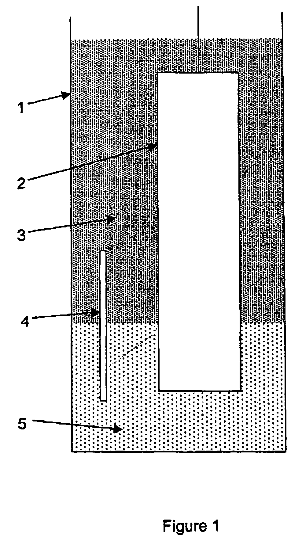
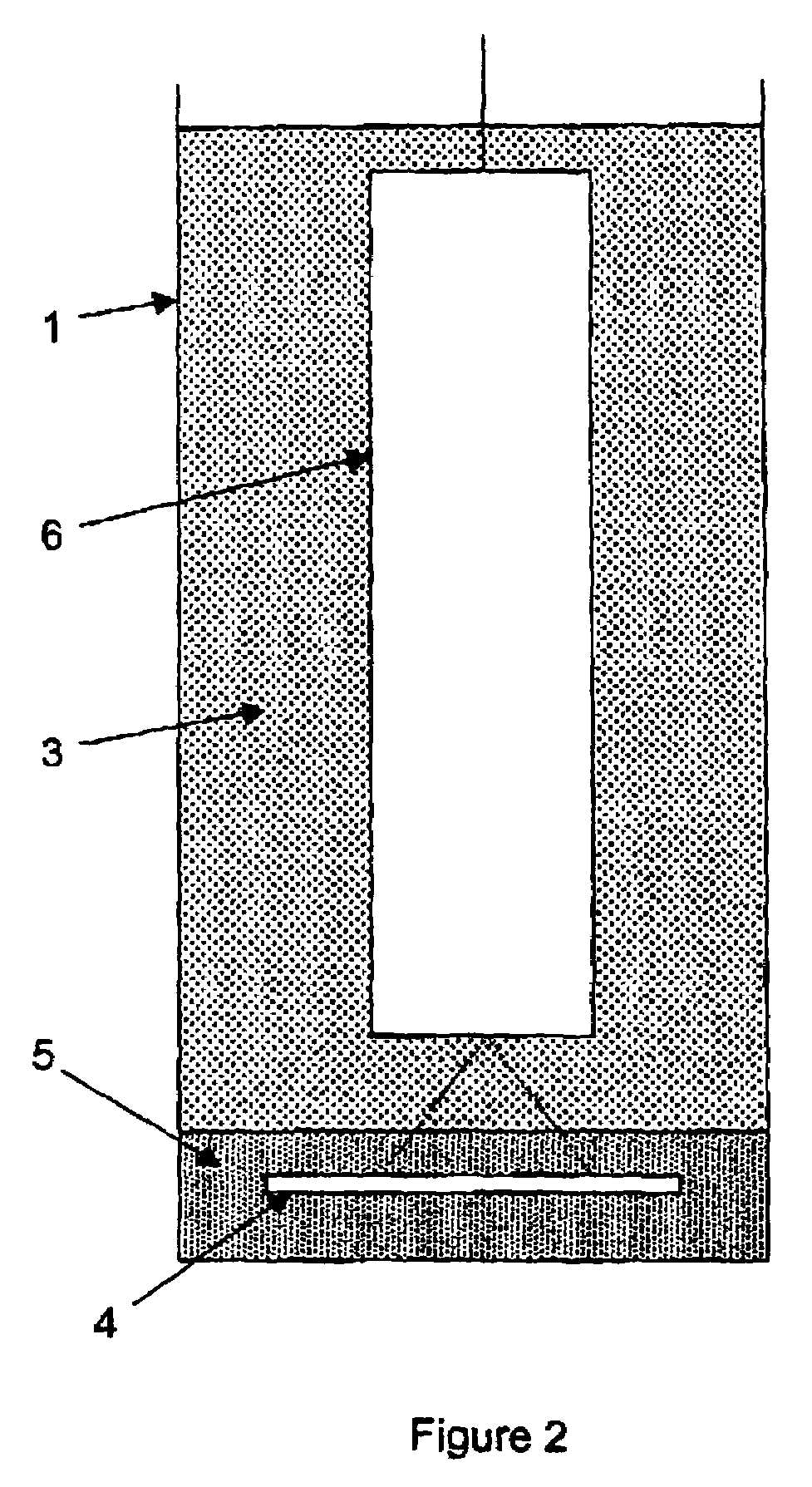
[0066]FIG. 1 shows a schematic diagram of a structure 1 in which a sideways-looking embodiment of the image sensor 2 is immersed in medium 3 and medium 5. The target 4 is viewed by the image sensor while straddling the boundary between the two media. The figure shows the image sensor deployed in the vertical axis, but, with an appropriate delivery mechanism, it may be deployed in any orientation.

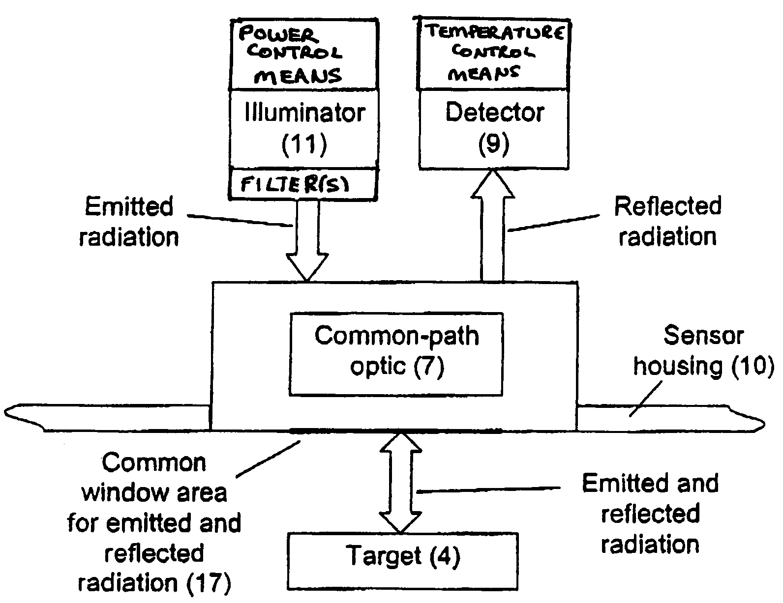
[0067]To view and image the target 4, the image sensor 2 emits radiation at wavelengths which are transmitted by each media 3 and 5. For example, if medium 5 is crude oil, and medium 3 is water, the sensor will emit radiation in the 1500–1650 nm waveband, and also in the visible-1350 nm waveband. This may be achieved in various ways. For example, sensor 2 may comprise light emitting or laser diodes, or groups of diodes, which operate in the respective wavebands and, for simultaneous imaging in both media, both diodes or groups of diodes will be operated as illumination sources. Alternatively...


PUM

PropertyMeasurementUnit
wavelengthaaaaaaaaaa
wavelengthsaaaaaaaaaa
poweraaaaaaaaaa

Abstract

The present invention relates to an in-vessel or down-hole optical imaging sensor or system for operating in structures which may contain media with different spectral transmission characteristics. The imaging sensor of the present invention selectively emits and/or detects two or more independently controllable wavelengths or wavebands. The imaging sensor comprises an illuminator for emitting radiation of a specified wavelength or waveband through a medium to a target, at least one detector for detecting the radiation deflected by said target and at least one amplifier for providing non-linear amplification of the detector output.

Description

CROSS-REFERENCE TO RELATED APPLICATIONS[0001]The present patent application claims priority from Great Britain Patent Application No. 0301447.9, filed on Jan. 22, 2003.BACKGROUND OF THE INVENTION[0002]1). Field of the Invention[0003]The present invention relates to an optical system image sensor operating in structures which may contain media with different spectral transmission characteristics; for example, in vessels containing both crude oil and water, either by rendering all media transparent simultaneously, or, on command, by rendering one or more of the media opaque to allow its detection.[0004]2). Discussion of Related Art[0005]In the oil industry, amongst others, it is necessary to inspect surfaces for cracks, corrosion, scale or other defects or characteristics, to examine welds to establish the integrity of a structure and ascertain the need for repair or replacement. It is desirable to use a single sensor to inspect internal surfaces of structures such as tanks, wells and...

Claims


Application Information

Patent Timeline
Patent Type & Authority Patents(United States)
IPC IPC(8): G01N21/00G01V3/18E21B47/00
CPCE21B47/0002E21B47/002H04N7/183
Inventor HOTHER, JOHN ANTHONYCOCKSHOTT, ROBERT ALEXANDER
Owner PRONETA
Why Eureka
Try Eureka