Process for manufacturing a micro-structured optical fibre

a manufacturing process and microstructure technology, applied in the field of microstructured optical fibre manufacturing, can solve the problems of difficult extraction of preforms from moulds, and achieve the effects of slow cooling down, small values of ration d/d, and low quality of optical preforms

Inactive Publication Date: 2007-05-01
PRYSMIAN CAVI E SISTEMI ENERGIA
View PDF11 Cites 14 Cited by
  • Summary
  • Abstract
  • Description
  • Claims
  • Application Information

AI Technical Summary

Benefits of technology

[0044]The method adopted for consolidation in a mould and extraction from the mould removes many technical drawbacks of the stack-and-draw method, as the presence of undesired interfaces carrying impurities, whereas the multi-step stretching and sleeving procedure allows obtaining small values of the ration d/D by using simple moulds.
[0045]Applicant has remarked, however, that it is difficult to achieve in practice a constant and reproducible diameter for the stretched preform resulting from the stretching operation. A diameter variation along a same stretched preform can significantly lower the quality of the optical preforms produced by the process and/or give rise to a large scrap, while a change of diameter from a stretched preform to the next one results in the need of adding material of

Problems solved by technology

In this case, however, it has been found that the extraction of the preform from the mould is made particularly difficult by th

Method used


Image

  • Process for manufacturing a micro-structured optical fibre
  • Process for manufacturing a micro-structured optical fibre
  • Process for manufacturing a micro-structured optical fibre

Examples


example

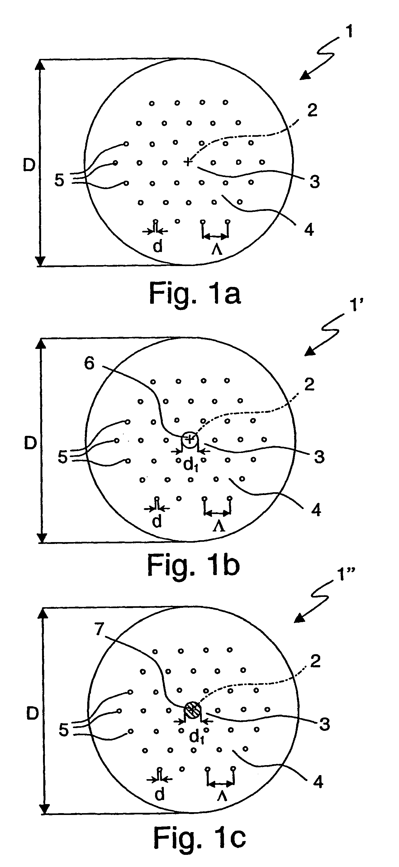
[0100]Two coaxial crowns of holes are arranged around a central defect, consisting of a missing hole. The field amplitude distribution of the fundamental mode has been calculated for this structure by using the values of 1.4892 for the bulk refractive index and 650 nm for the wavelength, both values being typical of polymethylmethacrylate. As an example, the results for Λ=10 μM (Λ / λ=15.4), and d=1 μm (d / Λ=0.1) have been evaluated. In these conditions, the 1 / e equal intensity line falls inside the solid core, close to the inner crown of holes, and the effective area at 650 nm results as large as 680 μm2.

[0101]Therefore the connection between fibres of this type is eased. The plastic material is easy to cut and splice; moreover, the large effective area reduces alignment difficulties.

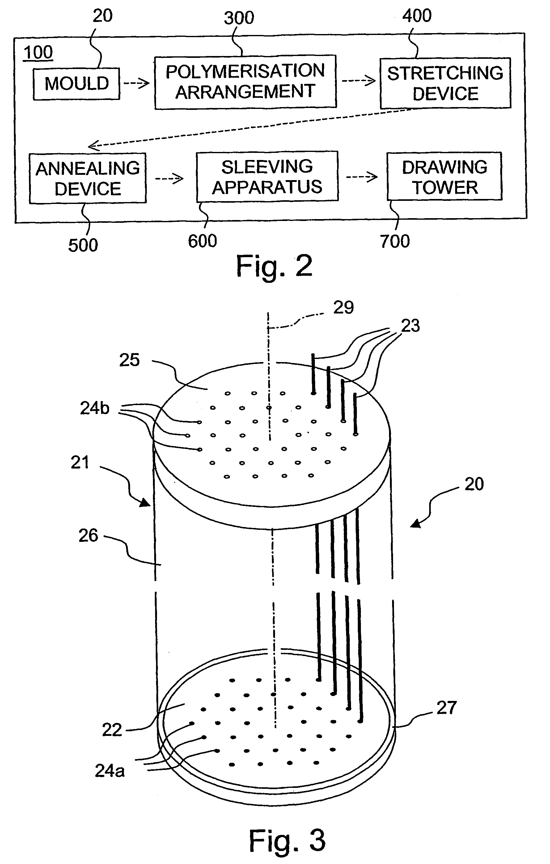
[0102]An assembly apt to manufacture micro-structured fibres of the types previously described is schematically depicted in the block representation of FIG. 2 and is here indicated with 100. Assembly 100 ...

example 1

[0181]500 ml of commercial methyl methacrylate (MMA) 99% (Sigma-Aldrich) were purified by passing through basic activated alumina powder (Sigma-Aldrich) in a glass column. The treatment removed the inhibitor and other impurities, supplying MMA of purity 99.7%.

[0182]The purified MMA was filtered with a 0.45 μm filter and inserted in a glass ampoule; 0.05% by weight of lauroyl peroxide 97% (Sigma-Aldrich) as initiator and 0.43% by weight of 1-decanethiol 96% (Sigma-Aldrich) as chain transfer agent were added. This mixture, freshly prepared or maintained at 4° C. in a refrigerator for a few days, was used for all the subsequent examples.

example 2

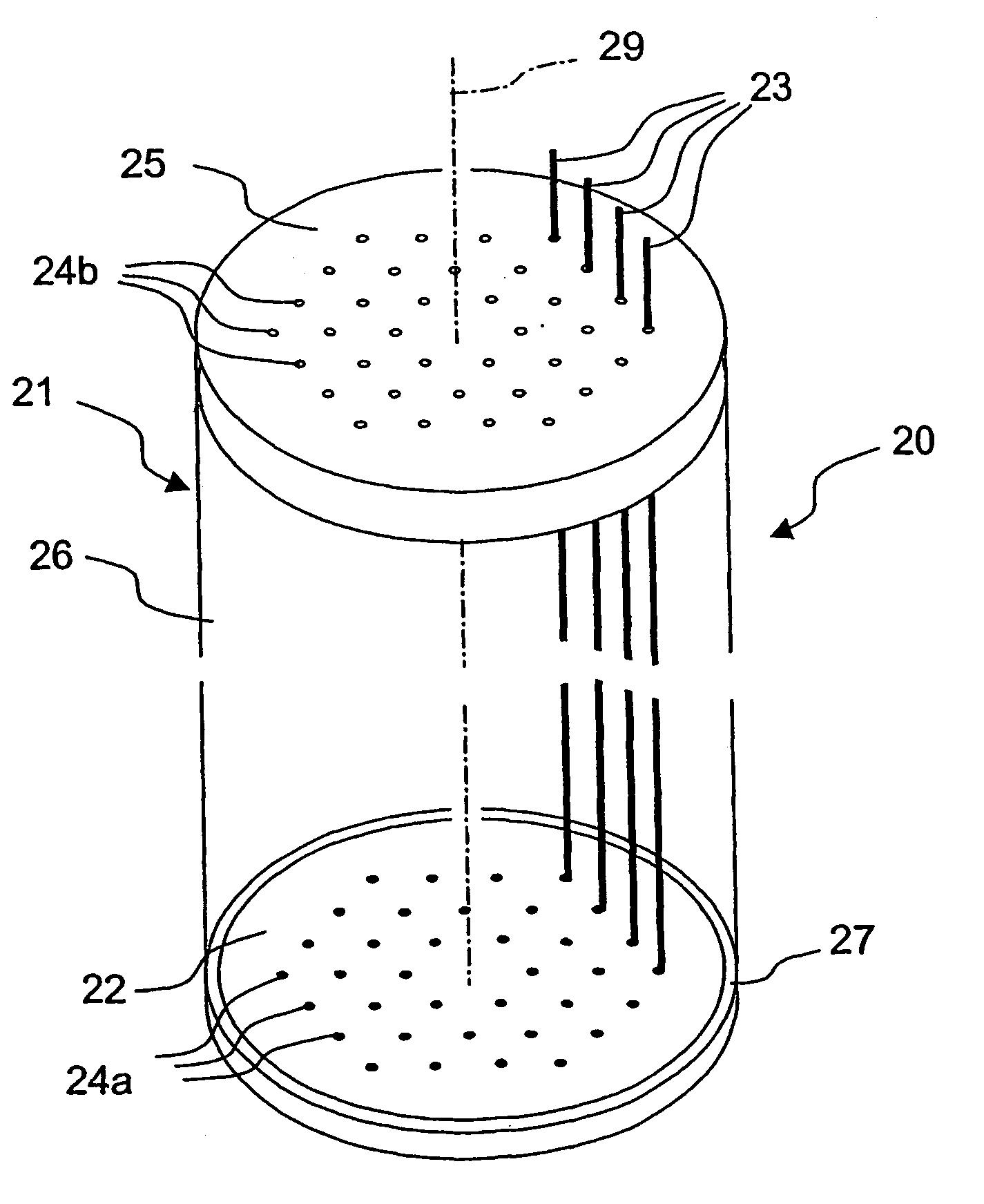
[0183]The container was a glass tube of internal diameter 28 mm, and length 250 mm. Two orders of holes, 0.55 mm in diameter, spaced 5.5 mm, were drilled on two aluminium covers, in a regular triangular arrangement around a central missing hole (FIG. 2). Stainless-steel wires of diameter 0.5 mm were inserted into the mould passing through both covers, which were fixed at the extremities of the tube by means of tie rods. The wires were bent at one edge and the other edge was inserted in and fixed to a template frame connected to the upper cover by threaded rods with nuts, which were used to tension the wire assembly. Tetrafluoroethylene seals and rubber o-rings were interposed between the covers and the glass tube, while the outer part of the covers was encapsulated in a polyurethane potting.

[0184]The mould so assembled was extensively cleaned from dust by means of a filtered solvent (ethyl alcohol) which was re-circulated through it with a peristaltic pump. The solvent was filtered ...


PUM

PropertyMeasurementUnit
Temperatureaaaaaaaaaa
Pressureaaaaaaaaaa
Angleaaaaaaaaaa

Abstract

An intermediate polymer preform of elongated shape for manufacturing a microstructured optical fibre is made from a mould with a tubular par containing a pattern of hole generating elements (wires, rods or tubes) extending along it. The hole generating elements are releasably attached to an upper and to a lower base of the mould. The mould is cleaned by circulating a filtered solvent in it. The mould is filled with a fluid polymer optical material or polymer precursor. The polymer material or precursor is consolidated so that it cannot change its shape under operating stress conditions at ambient temperature. The hole generating elements are released from the upper and lower base. The consolidated core preform is extracted from the mould. The process can further include calibrating the intermediate preform.

Description

CROSS REFERENCE TO RELATED APPLICATION[0001]This application is a national phase application based on PCT / EP02 / 04203, filed Apr. 16, 2002, the content of which is incorporated herein by reference.BACKGROUND OF THE INVENTION[0002]1. Field of the Invention[0003]This invention relates to a process for manufacturing a micro-structured optical fibre and to a method for producing a structured intermediate preform to be used in such a process.[0004]2. Description of the Related Art[0005]Optical fibres are used for transmitting light from one place to another. Normally, optical fibres are made of more than one material. A first material is used to form a central light-carrying part of the fibre known as the core, while a second material surrounds the first material and forms a part of the fibre known as the cladding. Light can become trapped within the core by total internal reflection at the core / cladding interface.[0006]A more recent type of optical fibre waveguide, having a significantly...

Claims


Application Information

Patent Timeline
IPC IPC(8): G02B6/02B29D11/00G02B6/12
CPCB29C55/00B29C61/003B29C71/02B29D11/00721G02B6/02033G02B6/02314G02B6/02347B29C2071/022G02B6/02328G02B6/02333G02B6/02338G02B6/02385
Inventor ARIMONDI, MARCOMACCHETTA, ANDREAASNAGHI, DANIELACASTALDO, ANNA
Owner PRYSMIAN CAVI E SISTEMI ENERGIA
Why Eureka
Try Eureka