

Process for upgrading heavy oil using a highly active slurry catalyst composition
a technology of slurry composition and heavy oil, which is applied in the direction of catalyst activation/preparation, hydrocarbon oil cracking, physical/chemical process catalysts, etc., can solve the problems of not demonstrating the criticality of oil viscosity, maintenance significance, etc., and achieves high viscosity carbonaceous
- Summary
- Abstract
- Description
- Claims
- Application Information
AI Technical Summary
Benefits of technology
Problems solved by technology
Method used
Image

Examples
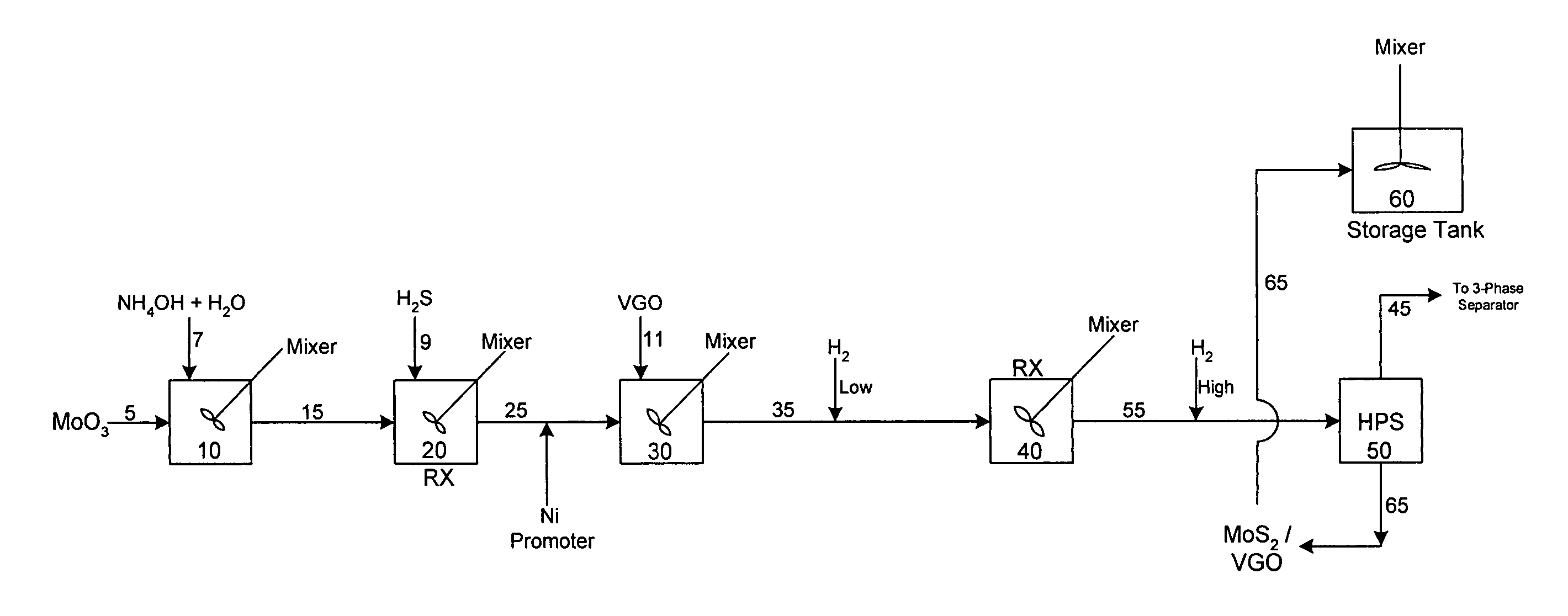
example 1
Catalyst Preparation Employing a Single Oil
[0034]540 gram MoO3 is mixed with 79 gram of NH3 and 2381 gram of H2O to form a solution of total 3000 gram. The solution is then reacted with 10.71 SCF of H2S by passing a gas mixture of 20% H2S in H2 into the solution under strong mixing. The reactor temperature is 150° F. and the total pressure is 400 psig, and the reaction time is 4 hours. After reaction, 460 gram NiSO4 solution which contains 36 gram of Ni is added to the above obtained slurry. The obtained slurry mixture is then mixed with 8000 gram of vacuum gas oil at 100° F. The viscosity of the VGO is 5 cSt @ 212° F. The resulting mixture is then pumped into a continuously flow tanked reactor (perfectly mixed flow reactor) with H2. The H2 gas rate is 300 SCF / B. The reactor pressure is 400 psig and reactor temperature is 400° F., the total reaction time is 1 hour. The reaction products are mixed with more H2 at a gas rate of 1500 SCF / B and then go to a hot high pressure separator. ...
example 2
Heavy Oil Upgrading (Athabasca Vacuum Residuum in Once-Through Mode)
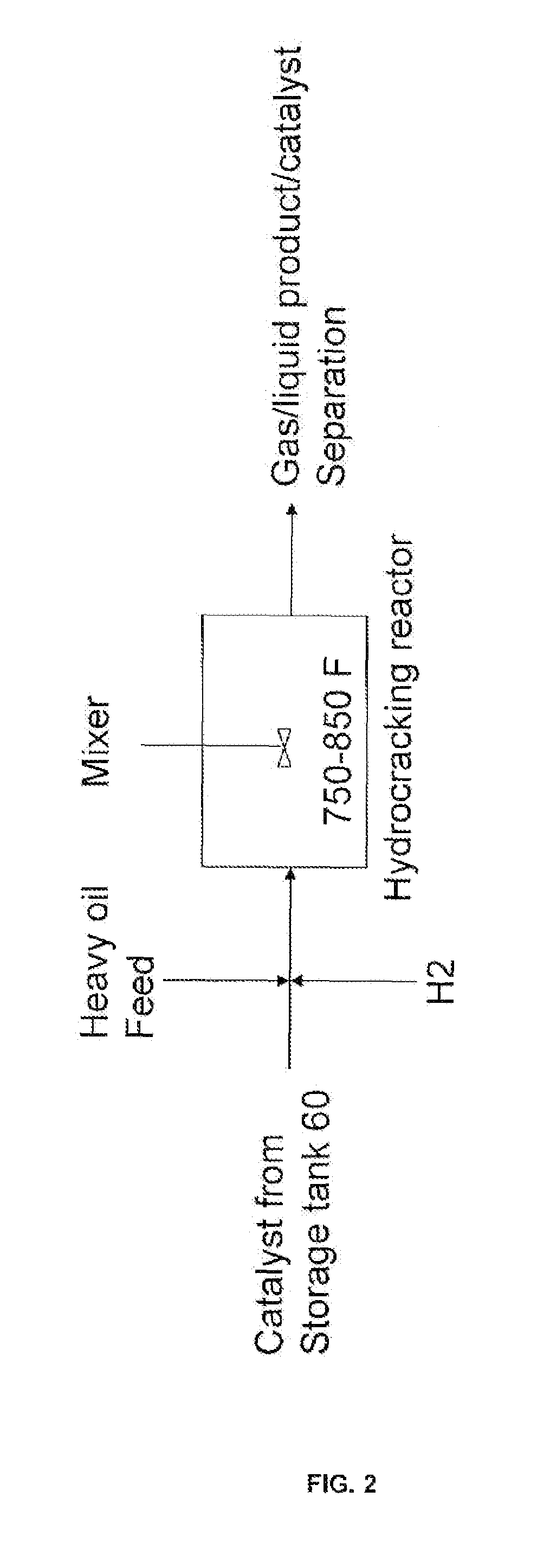
[0035]The catalyst slurry of Example 1 was used for Athabasca vacuum residuum and VGO feed upgrading in a process unit which contains two continuously stirred tank reactors. A feed blend with 60% Athabasca vacuum residuum (VR) and 40% Athabasca VGO was used.
[0036]The Athabasca VR feed properties are listed in the following table:
[0037]
API gravity at 60 / 603.9Sulfur (wt %)5.58Nitrogen (ppm)5770Nickel (ppm)93Vanadium (ppm)243Carbon (wt %)83.57Hydrogen (wt %)10.04MCRT. (wt %)17.2Viscosity @ 212° F. (cSt)3727Pentane Asphaltenes (wt %)13.9Fraction Boiling above 1050° F. (wt %)81
[0038]The Athabasca VGO feed properties are listed in the following table:
[0039]
API gravity at 60 / 6015.6Sulfur (wt %)3.28Nitrogen (ppm)1177Carbon (wt %)85.29Hydrogen (wt %)11.01MCRT (wt %)0.04Fraction Boiling above 650° F. (wt %)85
[0040]Hydrocracking reaction conditions include a reaction temperature between about 250° C. and about 500° C. (482° F....
PUM
| Property | Measurement | Unit |
|---|---|---|
| pressure | aaaaa | aaaaa |
| temperature | aaaaa | aaaaa |
| pressure | aaaaa | aaaaa |
Abstract
Description
Claims
Application Information