Liquid crystal optical modulator and drive method

a technology of optical modulator and liquid crystal, applied in the direction of instruments, computing, electric digital data processing, etc., can solve the problems of large device, large device, and large device size, and improve the directivity of antennas

Active Publication Date: 2007-05-15
CITIZEN WATCH CO LTD
View PDF4 Cites 5 Cited by
  • Summary
  • Abstract
  • Description
  • Claims
  • Application Information

AI Technical Summary

Benefits of technology

[0033]It is an object of the present invention to provide a liquid crystal optical modulator that solves the problems described above and to provide a liquid crystal optical modulator and its drive method that make it possible to vary not only the conventional convex operation but also the concave operation.
[0034]It is another object of the present invention to provide a liquid crystal optical modulator and its drive method suitable for forming a high-aperture rate, simply structured, and easy-to-drive micro lens array.
[0037]A liquid crystal optical modulator of the present invention has a liquid crystal molecule layer between a first substrate having thereon a plurality of stripe electrodes arranged in a stripe pattern and a second substrate having thereon opposed electrodes, and is capable of causing a modulation in a refractive index of the liquid crystal molecule layer by applying different voltages to both ends of the stripe electrodes. The second substrate has divided opposed electrodes each corresponding to a predetermined area on the stripe electrodes. The voltages are applied to the stripe electrodes and the opposed electrodes to cause the liquid crystal optical modulator to use a curve modulation area indicating characteristics that a birefringence for the voltage applied to the liquid crystal molecule layer is downwardly convex, or a curve modulation area indicating characteristics that the birefringence is upwardly convex, as a modulation area of the refractive index of the liquid crystal molecule layer. This causes the liquid crystal optical modulator to operate as a concave lens or as a convex lens.

Problems solved by technology

However, the problem is that, even if the antenna diameter is increased to some degree, a wavefront distortion due to an atmospheric turbulence prevents antenna directivity from being improved, and the antenna gain from exceeding a predetermined value.
However, because the wavefront distortion depends largely on the measurement location and the season, multiple types of fixed-focus micro lens array must be prepared for exchange of the array according to the degree of a wavefront distortion to be measured.
The problem with exchanging the lens array is that the device becomes large and the time is required for the exchange.
Therefore, in this voltage range, it is difficult to use the liquid crystal optical modulator as a spherical lens.
The problem with the conventional configuration is that the modulator finds uses only in an application where a narrow focal point range is acceptable because the operation is limited to the convex lens operation.

Method used


Image

  • Liquid crystal optical modulator and drive method
  • Liquid crystal optical modulator and drive method
  • Liquid crystal optical modulator and drive method

Examples


first embodiment

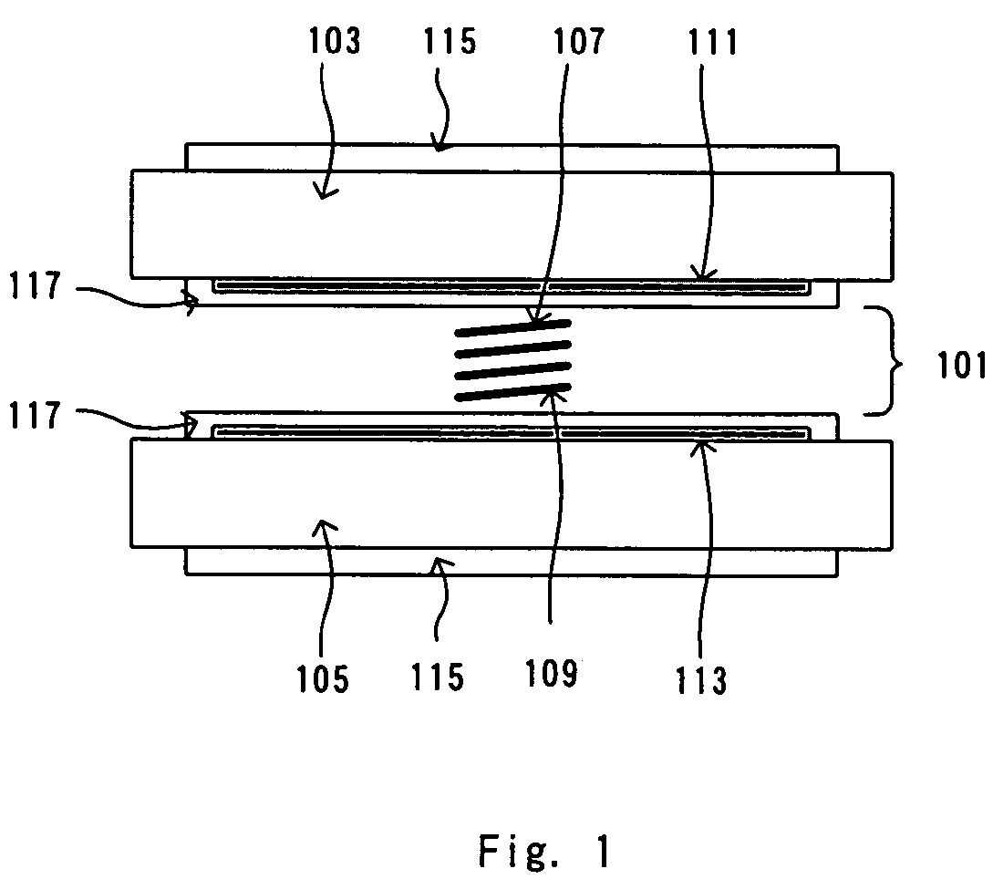
[0097]First, the configuration of a liquid crystal optical modulator in the present invention will be described with reference to the drawings. FIG. 1 is a cross section diagram showing the configuration of the liquid crystal optical modulator in the embodiment of the present invention. The cross section configuration is the same as that described in the description the prior art. Because the cross section configuration is the same as that of the liquid crystal optical modulator described in the prior art, the description is omitted here.

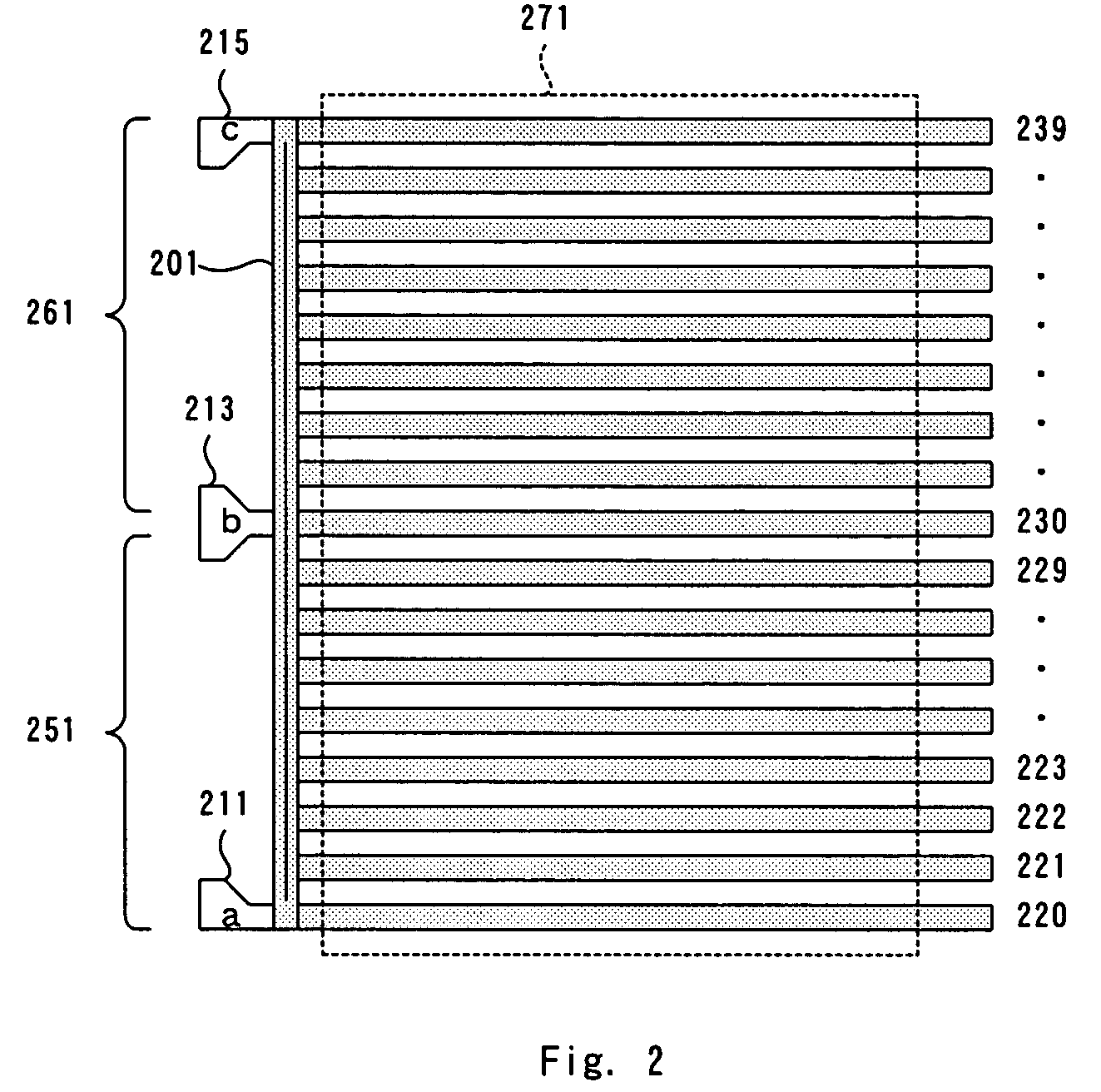
[0098]FIG. 2 is a top view of a composite electrode provided on the liquid crystal optical modulator, and FIG. 3 is a top view of an opposed electrode.

[0099]The configuration of the composite electrode 111 of the liquid crystal optical modulator of the present invention is the same as that for a method for implementing the conventional micro lens array of variable-focal length type. Only the configuration of the opposed electrode 113 (shown in FIG. ...

second embodiment

[0205]In the second embodiment, the configuration of a complex electrode for forming a spherical lens is the same as that used in the prior art. FIG. 29(a) is a top view showing the configuration of a composite electrode 2400. In the composite electrode 2400 of a spherical lens with a circular aperture, a plurality of semicircular stripe electrodes 2401–2408 around a central electrode 2409 are electrically connected by one gradient potential electrode 2410. The both ends of the gradient potential electrode 2410 are connected to a first signal electrode 2431 and to a second signal electrode 2433 which also function as the circular aperture. The stripe electrodes and the signal electrodes are separated into two areas by a first slit 2421 and a second slit 2423.

[0206]The central electrode 2409 and the stripe electrodes each forming a semicircular shape are formed by a polycrystalline ITO transparent conductive film, and the gradient potential electrode 2410 is formed by an amorphous tr...


PUM

PropertyMeasurementUnit
pre-tilt angleaaaaaaaaaa
tilt angleaaaaaaaaaa
pre-tilt angleaaaaaaaaaa

Abstract

A liquid crystal optical modulator is operated as a concave lens using a quadratic curve modulation area of a refractive index modulation area of a liquid crystal molecule layer, which is different from a conventional convex lens operation area, without changing the configuration of the liquid crystal optical modulator. In addition, the liquid crystal optical modulator is operated as a concave lens using a quadratic curve modulation area used by a conventional liquid crystal optical modulator as well as an area different from that area to enable the liquid crystal optical modulator to operate as a convex lens and as a concave lens. This makes it possible to perform the concave lens operation, to enlarge the variable focal range, and to form a micro-lens array of variable focal point type.

Description

BACKGROUND OF THE INVENTION[0001]1. Field of the Invention[0002]The present invention relates to a liquid crystal optical modulator, and more particularly to a liquid crystal optical modulator which allows an adaptive optics technology to be used for maintaining a reliable optical communication link in free space optical communication between satellites, between ground station and satellite, or between ground stations, which can operate as a concave lens or a convex lens, and which can vary the operation of a concave lens and a convex lens.[0003]2. Description of the Prior Art[0004]To increase the laser communication speed, it is necessary to keep a per-bit light volume constant and to increase the whole light volume. To do so, it is important to increase the antenna gain of a transmitter and a receiver. In a free space optical communication such as a communication between a ground station and a satellite, an atmospheric turbulence in an optical transmission line disturbs the wavefr...

Claims


Application Information

Patent Timeline
Patent Type & Authority Patents(United States)
IPC IPC(8): G09G3/36G09G5/00G02F1/13G02F1/133G02F1/1343G02F1/139G02F1/29
CPCG02F1/134309G02F1/29G02F2001/294G02F2203/28G02F1/294
Inventor IDE, MASAFUMI
Owner CITIZEN WATCH CO LTD
Why Eureka
Try Eureka