Thin film perpendicular magnetic recording head, their fabrication process and magnetic disk drive using it

Inactive Publication Date: 2007-05-22
HITACHI GLOBAL STORAGE TECH JAPAN LTD
View PDF25 Cites 30 Cited by
  • Summary
  • Abstract
  • Description
  • Claims
  • Application Information

AI Technical Summary

Benefits of technology

[0062]The present invention can provide a thin film perpendicular magnetic recording head and magnetic disk drive capable of preventing erasur

Problems solved by technology

However these factors are nothing more than technical issues.
Increases in the linear recording density however are subject to basic restrictions due to the fact that the recording medium is an aggregate of ferromagnetic particles.
Problems such as shifts in the actual position of the magnetic reversal occur when adjoining magnetic transition areas interfere with each other in locations when the bit length is short.
These problems make it necessary to reduce the magnetic transition areas to at least a size smaller than the bit length.
In this case, when the magnetic coercivity of the recording layer of the medium exceeds 5 kOe, obtaining a magnetic recording field strong enough to magnetize the medium is difficult.
The thermal fluctuation becomes drastic, causing the problem that thermal decay reduces the magnitude of the record magnetization as time passes.
However as described above, there is an upper restriction on the allowable magnetic coercivity when the magnetic field of the head is limited.
However, attempting to attain a sufficient volume for the crystal grains longitudinally, increases the randomness of the magnetization distribution within the medium, leading to increased noise in the medium and preventing a sufficient S/N (signal-to-noise) ratio from being obtained.
Therefore, achieving longitudinal recording in excess of an areal recording density of 100 gigabits per square inch while satisfying the conditions for thermal decay, low noise and sufficient recording is predicted to be basically difficult.
The one serious problem unique to perpendicular recording utilizing the mutual effects of a single pole write element and magnetic flux keeper layer is the remanent magnetization of the main pole.
Therefore when this phenomenon occurs

Method used


Image

  • Thin film perpendicular magnetic recording head, their fabrication process and magnetic disk drive using it
  • Thin film perpendicular magnetic recording head, their fabrication process and magnetic disk drive using it
  • Thin film perpendicular magnetic recording head, their fabrication process and magnetic disk drive using it

Examples


first embodiment

[0107](First Embodiment)

[0108]FIG. 6 is a cross sectional view showing the structure of the magnetic multilayer of the first embodiment of the present invention. A high Bs layer 63 and a nonmagnetic layer 64 are alternately deposited on the substrate 61 by way of the underlayer 62, and finally covered by a protective layer 65. This high Bs layer 63 is Fe70Co30 having a body-centered cubic structure. The underlayer 62 and nonmagnetic layer 64 are both Ni80Cr20 (film thickness 3 nanometers) having a face-centered cubic structure. FIG. 6 shows the magnetic multilayer as seen from the medium surface facing the main pole.

[0109]The thickness of each high Bs 63 layer is calculated for a total high Bs layer thickness of 200 nanometers so each layer in the example in FIG. 6 is 25 nanometers. The low Bs layer is nickel-chromium alloy and is 3 nanometers thick. Measuring the magnetization curves showed that the magnetic coercivity along the easy axis and the hard axis were both below 4 Oe, the...

second embodiment

[0128](Second Embodiment)

[0129]In the first embodiment, the layers were formed to the same thickness within a certain range (generally about ±5%) for variations during forming of the high Bs layer for the main pole. However, by purposely forming a structure of different thickness, even further improvements can be achieved.

[0130]FIG. 15 is a cross sectional view showing the structure of this type of embodiment. Here, a film thickness difference of 20 percent was made between a first high Bs layer (odd numbered high Bs layer from the substrate side) 63 and a second high Bs layer (even numbered high Bs layers from the substrate side) 63′ and these layers then alternately formed in a laminated structure. By utilizing this structure, an identical magnetic state can he constantly achieved for each magnetostatic coupling by high Bs layers in a remanent magnet state. Consequently, the same characteristics appear for 1010 cycles of write operations which is an extremely large number, showing...

third embodiment

[0131](Third Embodiment)

[0132]An example of the second embodiment with high Bs layers of the main pole having different structures for each layer is shown in FIG. 16. This embodiment has a structure where among the high Bs layers, the high Bs layer nearest the substrate and the high Bs layer farthest from the substrate are made thinner than the other high Bs layers. In this structure, since these two layers have only a high Bs layer on one side, the weak remanent magnetic fields are not applied to the media. It was also found that satisfactory read / write characteristics can be obtained with no loss in long term stability of bits written on the magnetic record medium.

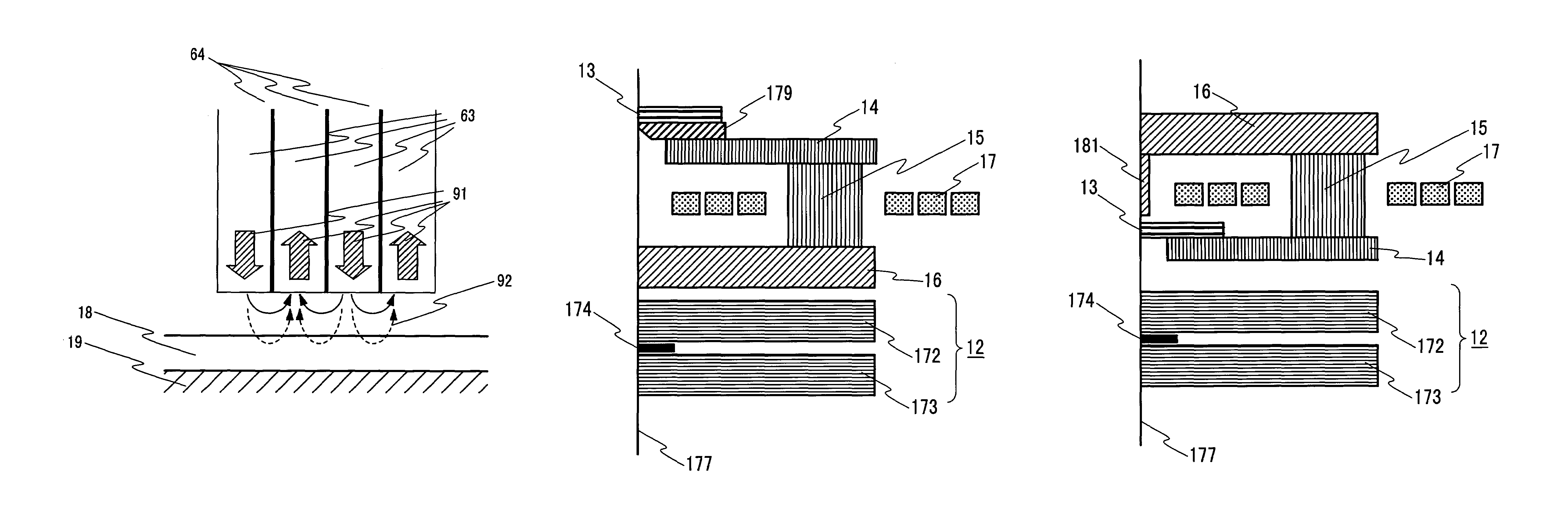
[0133]The structure of the write element used in all of the embodiments up to now is shown in FIG. 8. The following embodiments of the present invention are for a thin film magnetic head other than the structure shown in FIG. 8.


PUM


Abstract

Thin film perpendicular magnetic head with a narrow main pole capable of a high recording density in excess of 100 gigabits per square inch and generating a high magnetic recording field exceeding 10 kOe while suppressing remanent magnetic fields occurring immediately after write operations. The perpendicular magnetic head comprises a main pole, a return path for supplying a magnetic flux to that main pole, and a conductive coil for excitation of the main pole and return path. The main pole has a pole width of 200 nanometers or less, and a magnetic multilayer made up of a high saturation flux density layer and low saturation flux density layer. The low saturation flux density layer has a thickness within 0.5 to 5 nanometers, and The high saturation flux density layer has a thickness from 10 to 50.

Description

BACKGROUND OF THE INVENTION[0001]1. Field of the Invention[0002]The present invention relates to a thin film perpendicular magnetic recording head, their magnetic head fabrication process and magnetic disk drive for a highly reliable magnetic head with stable operation capable of generating a high magnetic recording field even on narrow tracks for high density magnetic recording.[0003]2. Description of Related Art[0004]In recent years, digitalization of diverse media has been making rapid progress along with advancements in information processing technology. Besides personal computers and servers, home appliance and audio devices must store huge amounts of digital information, creating an increasing demand greater than ever before for large capacity magnetic disk drives forming the core of non-volatile file systems. Large capacity disk drives in other words signifies recording on a medium with a higher bit density or in other words, a higher areal recording density.[0005]A method ca...

Claims


Application Information

Patent Timeline
IPC IPC(8): G11B5/147G11B5/39G11B5/127G11B5/31G11B5/66
CPCG11B5/1278G11B5/3906
Inventor KAWATO, YOSHIAKINAKAMOTO, KAZUHIROHOSHIYA, HIROYUKIOKADA, YASUYUKIMOCHIZUKI, MASAFUMI
Owner HITACHI GLOBAL STORAGE TECH JAPAN LTD
Why Eureka
Try Eureka