Valve body with integral seal retention groove

a technology of sealing groove and valve body, which is applied in the field of valves, can solve the problems of increasing the stress of impact loading, exacerbate sealing problems, and high manufacturing cost of above-valve valves, and achieves the effects of low manufacturing cost, light weight and easy fabrication

Inactive Publication Date: 2007-05-29
NOVATECH HLDG CORP
View PDF6 Cites 51 Cited by
  • Summary
  • Abstract
  • Description
  • Claims
  • Application Information

AI Technical Summary

Benefits of technology

[0033]Thus, valve bodies of the invention, whether comprising one or a plurality of interior hollows, are strong and stiff but relatively light-weight compared to competing designs. They are relatively easy to fabricate and require relatively little f

Problems solved by technology

However named, the above valves are expensive to manufacture, especially the moving portion or valve body.
Prior efforts to reduce distortion under load by strengthening such valve bodies have generally resulted in higher cost and/or heavier designs which exacerbate sealing problems and/or increase the stress of impact loading on components of the valve assembly.
Commercially important design improvements necessarily reflect the fact that certain mud pump valve body and seat dimensions are effectively limited by industry practices and American Petroleum Institute (API) Standards.
Given these constraints, attempts to reduce fatigue failures and/or improve valve performance have led to “improved” designs which are more expensive to manufacture and have different failure modes than earlier versions.
But such valve bodies have several disadvantages in manufacture and use.
First, rough valve body forgings in the Channel-Beam shape require substantial material removal in finish machining of the integral seal retention groove.
Second, an elastomeric seal snapped into the seal retention groove may not fully seat around the entire valve body, causing an out-of-round condition that can result in early valve failure.
Avoidance of thin portions, on the other hand, imposes weight penalties that result in greater impact loading.
Notwithstanding their relatively high cost, however, valve bodies having an integral seal retention groove (i.e., a seal retention groove having no removable seal retention plate or other analogous removable structural member) such as the one-piece Channel-Beam design have gained limited industry acceptance.
Distortion about radial axes is particularly a problem on valve bodies that mate with web seats.
Cyclical high pressure applied to a valve body when it is sealed against a web seat is especially damaging, tending to repeatedly force portions of the valve body into the spaces between the seat webs.
On multi-piece valve bodies (i.e., valve bodies having a removable seal retention plate), cyclic loading as d

Method used


Image

  • Valve body with integral seal retention groove
  • Valve body with integral seal retention groove
  • Valve body with integral seal retention groove

Examples


Embodiment Construction

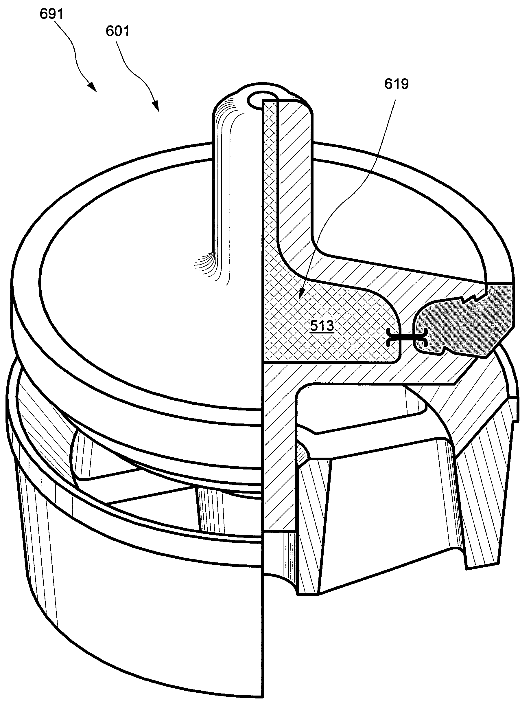
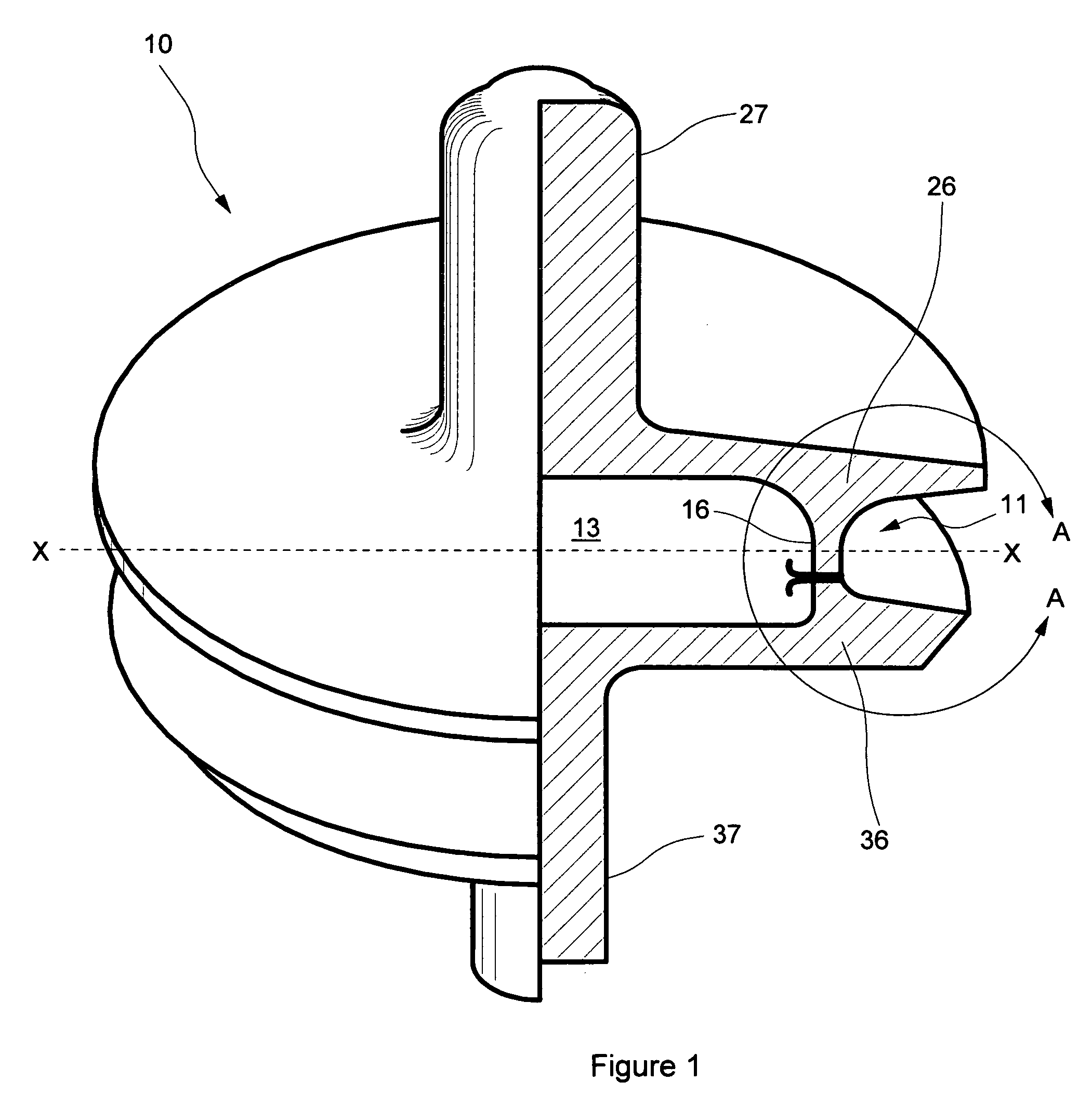
[0058]FIG. 1 illustrates a schematic view with partial cross-section of a valve body 10 for use in web-seat, stem-guided valves. Valve body 10 comprises integral seal retention groove 11, cylindrical web 16, first and second guide stems 27 and 37 respectively, and hollow 13. Seal retention groove 11 is machined smooth to accept a snap-on elastomeric seal. The area encircled by line A—A functions in a manner analogous to a theoretical I-beam wherein resistance to bending is always about an axis perpendicular to cylindrical web 16 (i.e., about a radial axis X—X). Thus, cylindrical web 16 functions to resist the wrinkling deformation described above. Note that the illustrated cross section encircled by line A—A in FIG. 1 suggests an I-beam shape, with the relatively lighter cylindrical web 16 positioned analogously to a web connecting the relatively heavier flange regions 26 and 36. In conjunction with its impact on a valve seat, the periphery of disc-shaped valve body 10 tends to be d...


PUM


Abstract

A valve body having at least one internal hollow or space comprises two separately formed portions joined by at least one cylindrical web. Internal space may communicate with space outside the valve body via a fluid passage, and internal space may be filled with a substantially incompressible flowable substance to facilitate pressure equalization across the valve body. Forging or casting valve body portions to near-net-shape prior to joining minimizes machining necessary to achieve a final desired shape. Increased valve durability and reduced metal wear arise from the reduced valve body weight and correspondingly reduced impact loading as the valve body moves to seal against a valve seat. A single-durometer or dual-durometer elastomeric seal may be cast and cured in place in a peripheral integral seal retention groove, coupled thereto in part through welding flash protruding into the groove and/or through at least one serration in the groove.

Description

[0001]This is a continuation-in-part (CIP) patent application of U.S. Ser. No. 10 / 715,043, which was filed Nov. 17, 2003 now U.S. Pat. No. 6,955,339.FIELD OF THE INVENTION[0002]The invention relates generally to valves suitable for abrasive fluids under high pressures. More specifically, the invention relates to valve bodies having at least one integral seal retention groove.BACKGROUND OF THE INVENTION[0003]A valve suitable for abrasive fluids such as oil field drilling mud comprises a valve body and a corresponding valve seat, with certain valve bodies incorporating an elastomeric seal within a peripheral seal retention groove. Such a valve is usually mounted in the fluid end of a pump incorporating positive displacement pistons or plungers in multiple cylinders. Such valves may be stem-guided full-open designs (i.e., having a top guide stem and a bottom crow-foot guide on the valve body) or web-seat, stem-guided designs (i.e., having top and bottom guide stems on the valve body). ...

Claims


Application Information

Patent Timeline
IPC IPC(8): F16K1/00F16K15/00
CPCF16K1/385Y10T137/7868
Inventor BLUME, GEORGE H.
Owner NOVATECH HLDG CORP
Why Eureka
Try Eureka