Solvent resistant bearings for self-generating electrostatic spray gun

a self-generating electrostatic spray gun and bearing technology, applied in sliding contact bearings, mechanical equipment, lighting and heating devices, etc., can solve problems such as bearing failure, and achieve the effect of prolonging the life of the bearing

Inactive Publication Date: 2007-06-05
GRACO INC
View PDF3 Cites 39 Cited by
  • Summary
  • Abstract
  • Description
  • Claims
  • Application Information

AI Technical Summary

Benefits of technology

[0006]It is the purpose of this invention to remove the aforementioned causes of failure and extend bearing life.

Problems solved by technology

During cleaning of the applicator with solvents, such liquid solvents can flow into the bearings through the air passages, causing the solvents to remove the lubricant from the bearings subsequently leading to bearing failure.

Method used


Image

  • Solvent resistant bearings for self-generating electrostatic spray gun
  • Solvent resistant bearings for self-generating electrostatic spray gun

Examples


Embodiment Construction

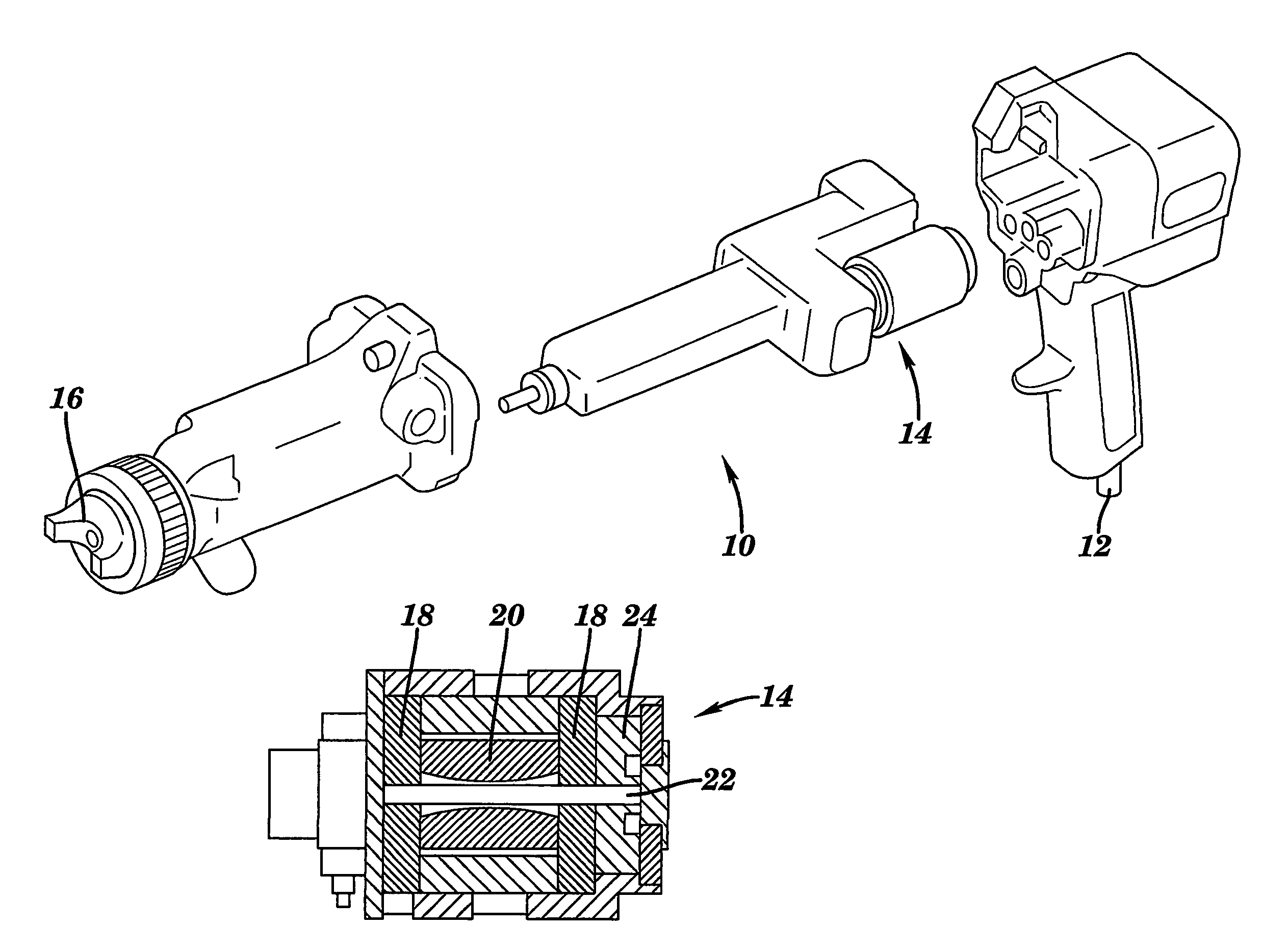
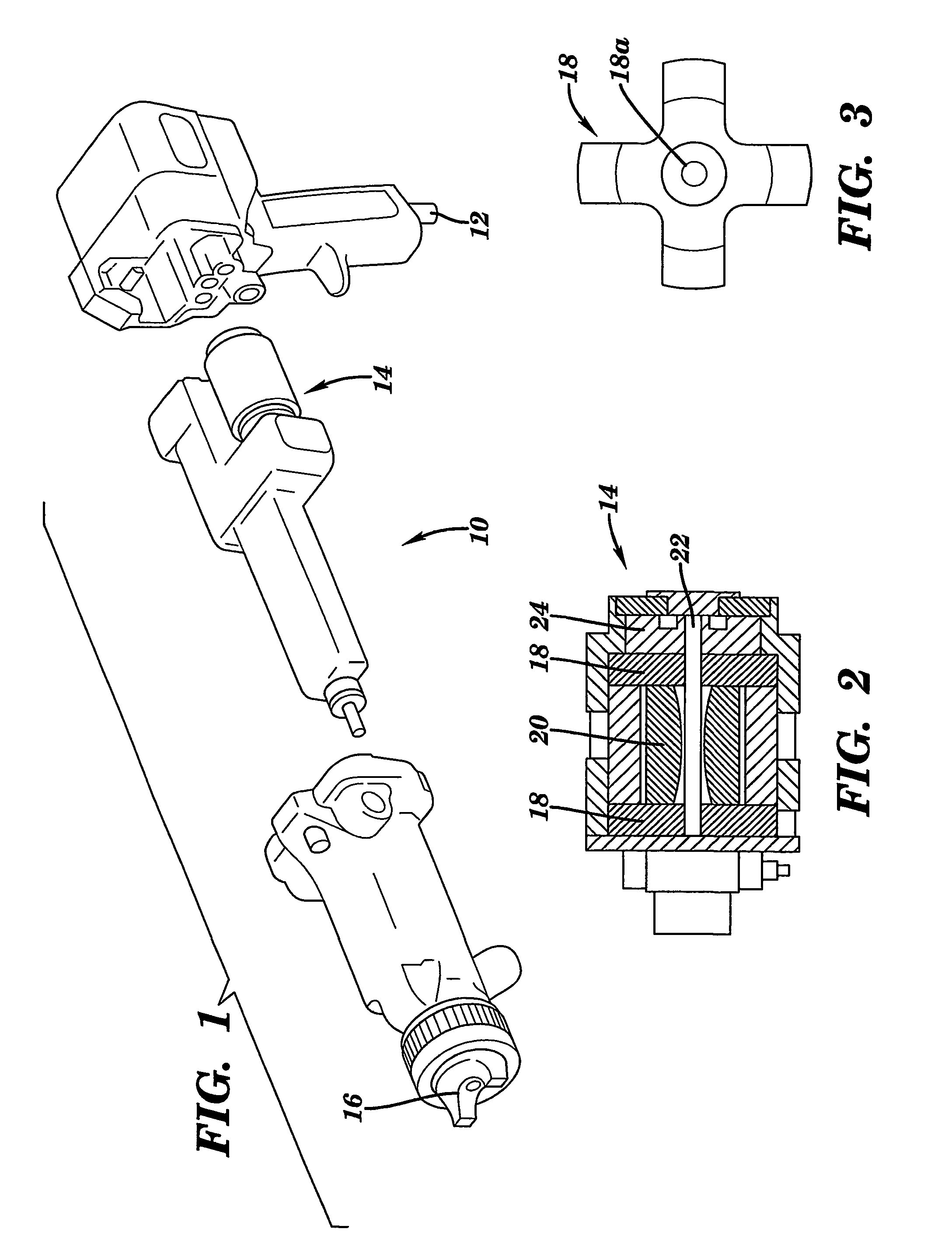
[0014]In the instant invention shown broadly in FIG. 1, an electrostatic gun, generally designated 10 has an inlet air passage 12, an alternator turbine assembly 14 and an air cap 16. Alternator assembly 14 is shown in more detail in FIG. 2, and is comprised of bearings 18, magnet 20 mounted on shaft 22, and impeller 24 mounted on shaft 22. Bearings 18 are shown in detail in FIG. 3 and are coated with XYLAN fluoropolymer based coating material (in the preferred embodiment), an epoxy-based paint or baked on powder coating except for the inner diameter 18A which is left uncoated.

[0015]After a curing of the coating, the bearings are placed in a container of lubricating oil and a vacuum drawn, thereby removing the air from the porous bearings and allowing the oil to penetrate the bearing for later use.

[0016]It is contemplated that various changes and modifications may be made to the bearing assembly without departing from the spirit and scope of the invention as defined by the following...


PUM


Abstract

An electrostatic spray gun (10) having an air powered alternator-turbine (14) with a rotating impeller (24) therein mounted in bearings (18) is provided with bearings (18) which are coated with a solvent resistant material. This coating is provided on all surfaces of the bearing (18) except for the inner diameter (18A) which contains the impeller (24). This construction prevents leaching of the oil out of the bearing (18) and into the airstream and also is resistant to paint should the spray gun (10) become immersed in such.

Description

[0001]This application is a 371 of PCT / US02 / 15925, filed May 16, 2002, which claims benefit of U.S. Provisional Application No. 60 / 291,269, filed May 16, 2001.TECHNICAL FIELD[0002]Electrostatic spray guns are well known for use in applying paints and other coatings where high transfer efficiency is preferred.BACKGROUND ART[0003]Electrostatic spray guns having self-contained power supplies such as shown in U.S. Pat. Nos. 4,554,622, 4,462,061, 4,290,091, 4,377,838 and 4,491,276 are well known. Such applicators have an air-powered turbine which drives an alternator which in turn supplies a voltage multiplier to provide the charging voltage.[0004]In such products, the bearings are used to hold and allow a magnet to rotate on its shaft. In normal operation, air is passed over an internal impeller causing the magnet to rotate and such rotation inside a coil of wire provides electrical power for the applicator. This air is then exhausted through a separated air passage to the outside of th...

Claims


Application Information

Patent Timeline
Patent Type & Authority Patents(United States)
IPC IPC(8): B05B5/00B05B5/053B05B5/025B05B5/08F16C17/24F16C33/20
CPCB05B5/0531F16C17/24F16C33/103F16C33/12F16C33/201B05B5/0532
Inventor LUNZER, LAWRENCE J.
Owner GRACO INC
Why Eureka
Try Eureka