Cast-iron insert and method of manufacturing same

a technology casting iron, which is applied in the field of cast iron inserts, can solve the problems that the inner surface of the cast iron inserts b>1/b> cannot be accurately machined, and achieve the effect of increasing the intimate contact with another metal effectively, simple process and desired level of accuracy

Active Publication Date: 2007-06-05
HONDA MOTOR CO LTD
View PDF33 Cites 19 Cited by
  • Summary
  • Abstract
  • Description
  • Claims
  • Application Information

AI Technical Summary

Benefits of technology

[0011]It is an object of the present invention to provide a cast-iron insert which can be brought into increased intimate contact with another metal effectively by a simple process and can be clamped in position with a desired level of accuracy.
[0012]Another object of the present invention is to provide a method of manufacturing a cast-iron insert which can be brought into increased intimate contact with another metal effectively by a simple process and can maintain a desired level of thermal conductivity.
[0014]The substantially conical undercuts that progressively spread outwardly from the surface of the cast-iron insert in various different directions allow the cast-iron insert and the other metal, e.g., an aluminum alloy, cast therearound to be held in intimate contact with each other. The protrusions have a much larger surface area than the conventional spines. When the cast-iron insert is actually used, the heat generated in the cast-iron insert by another member which slides against the cast-iron insert can well be transmitted to the aluminum alloy. Accordingly, the cast-iron insert has a high heat radiation capability.
[0015]The protrusions have respective flat faces on the distal ends of the undercuts or necks which are progressively spread outwardly from the surface of the cast-iron insert. Consequently, the area of contact between the outer circumferential surface of the cast-iron insert and the clamping surface of a clamp mechanism which clamps the cast-iron insert in position is much larger than the area of contact between the outer circumferential surface of the conventional spikes and the clamping surface. Stated otherwise, while the conventional spikes and the clamping surface are held in point-to-point contact with each other, the cast-iron insert and the clamping surface are held in face-to-face contact with each other. As a result, the cast-iron insert can be clamped in position with increased accuracy and hence can be machined neatly with increased accuracy.
[0018]Then, the existing atmosphere in the mold is replaced with the inactive gas atmosphere. Therefore, no oxide film is formed on the surface of the molten cast iron as it is poured in the mold. As a result, the molten cast iron has its fluidity kept well in the mold. Consequently, the molten cast iron flows smoothly in the mold and reliably fills the spaces around the spherical bulges and the undercuts. When the cast iron is cooled into the cast-iron insert, it has its surface shaped accurately complementarily to the surface configuration of the facing material.
[0019]Thus, the cast-iron insert has the protrusions, each with the substantially conical undercut or neck progressively spread outwardly, firmly and neatly formed on the surface thereof. The protrusions are highly effective to keep the cast-iron insert in intimate contact with the aluminum alloy cast therearound, and also make the cast-iron insert highly thermally conductive with respect to the aluminum alloy.

Problems solved by technology

Consequently, the inner surface of the cast-iron insert 1 cannot be machined accurately.

Method used


Image

  • Cast-iron insert and method of manufacturing same
  • Cast-iron insert and method of manufacturing same
  • Cast-iron insert and method of manufacturing same

Examples


Embodiment Construction

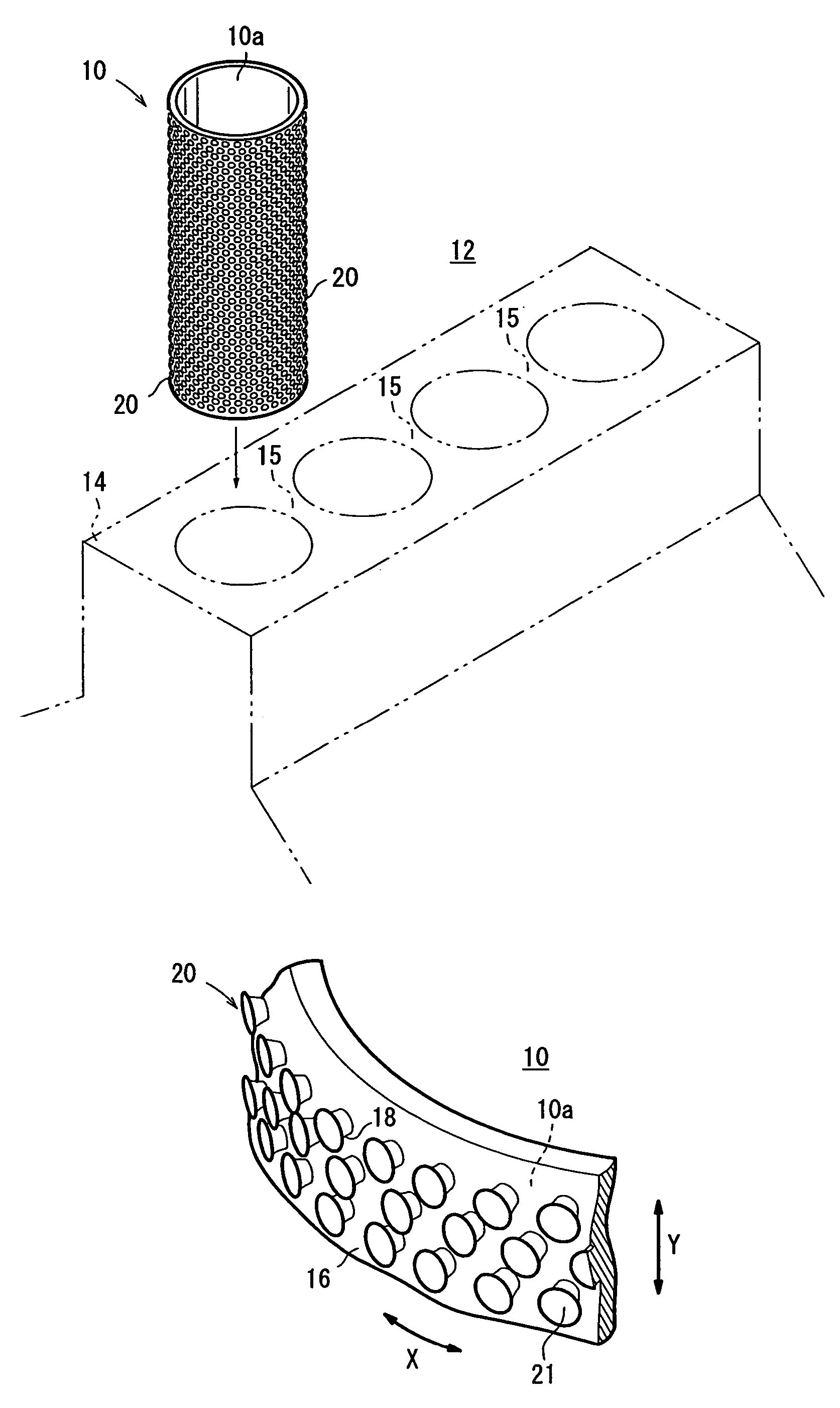
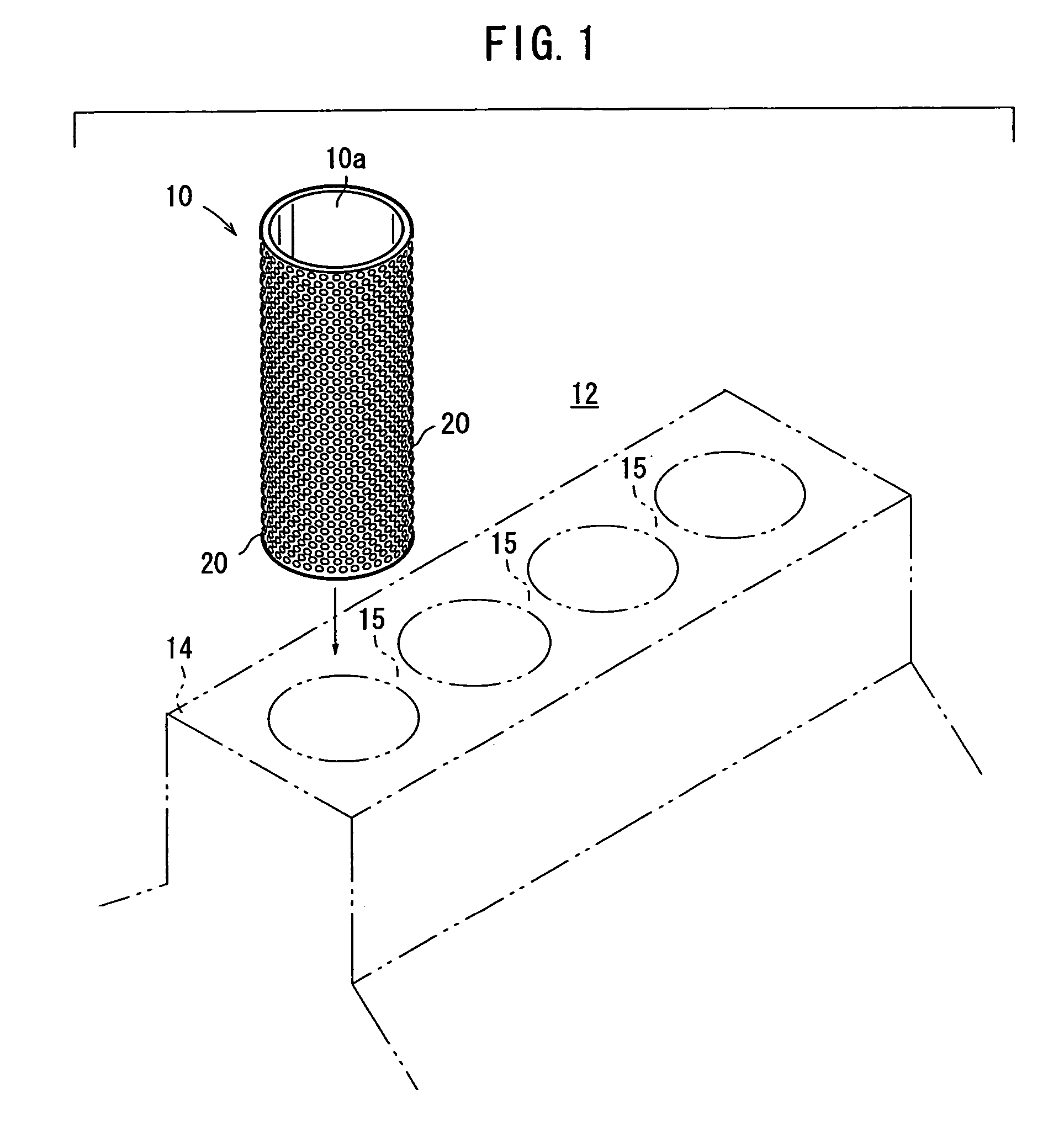
[0035]FIG. 1 shows in exploded perspective a cylinder block 12 to be cast around a cylinder liner or sleeve 10 as a cast-iron insert according to the present invention.

[0036]As shown in FIG. 1, the cylinder block 12 includes a block 14 made of an aluminum alloy, for example, to produce lighter engines. The cylinder block 12 also includes a plurality of cylinder liners or sleeves 10 (one shown) around which an aluminum alloy is cast as the block 14.

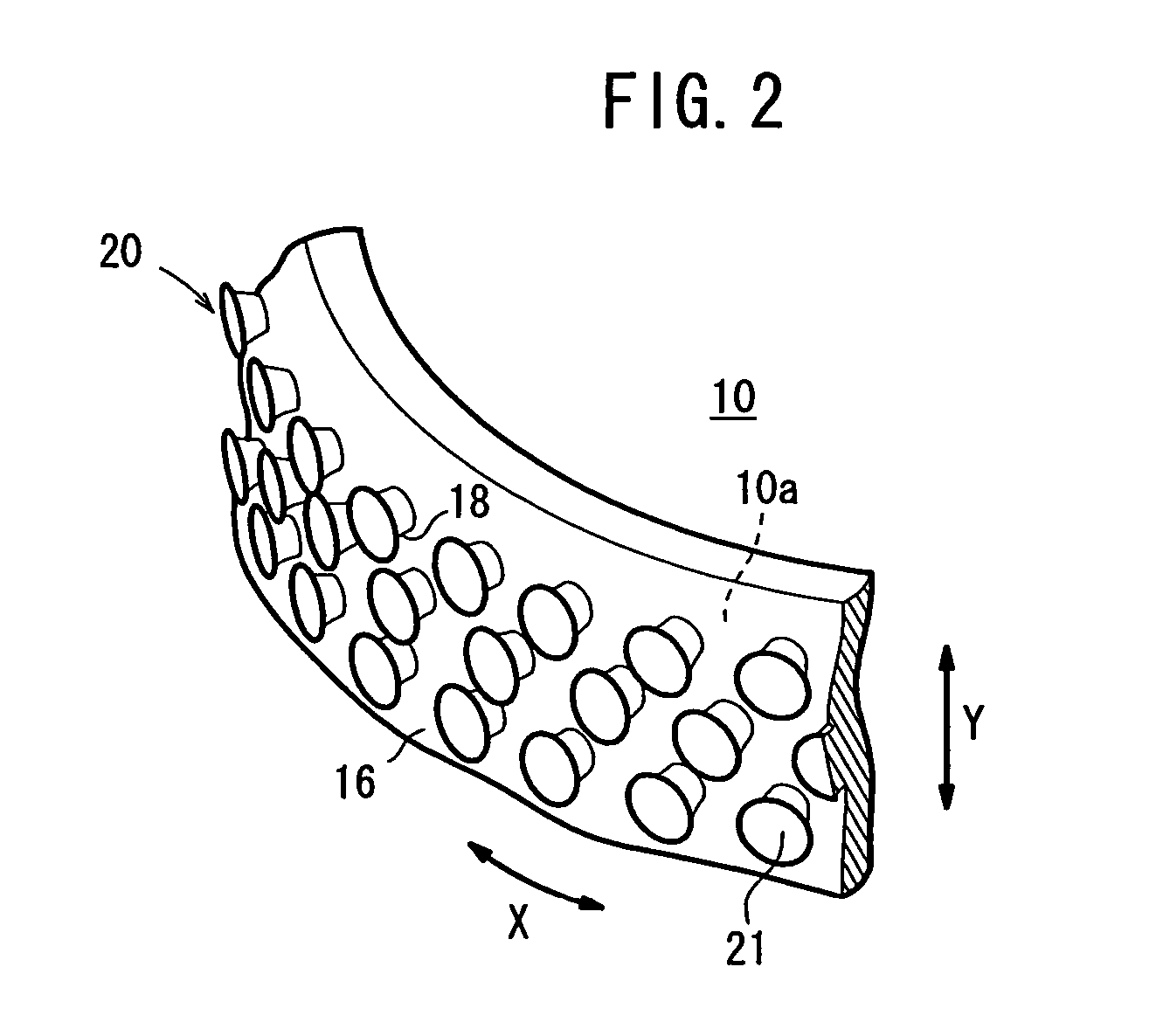
[0037]Each of the cylinder liners 10 is molded of cast iron according to a centrifugal casting process. As shown in FIG. 2, the cylinder liner 10 has a plurality of protrusions 20 disposed on an outer circumferential surface 16 thereof over which the aluminum alloy is to be cast. Each of the protrusions 20 has a substantially conical undercut or neck 18 which is progressively spread outwardly and a flat outer face 21 on the distal end of the undercut or neck 18.

[0038]If the outer circumferential surface 16 of the cylinder liner 10 has a di...


PUM

PropertyMeasurementUnit
heightaaaaaaaaaa
heightaaaaaaaaaa
diameteraaaaaaaaaa

Abstract

A cylinder liner has an outer circumferential surface around which another metal is to be cast. The cylinder liner also has a plurality of protrusions disposed on the outer circumferential surface and having respective substantially conical undercuts or necks which are progressively spread outwardly from the outer circumferential surface. The protrusions have respective flat faces on the distal ends of the undercuts.

Description

TECHNICAL FIELD[0001]The present invention relates to a cast-iron insert over which another metal, e.g., aluminum, is to be cast, and a method of manufacturing such a cast-iron insert.BACKGROUND ART[0002]For example, cylinder blocks for use in automotive engines are made of an aluminum alloy for producing lighter engines. The cylinder blocks include cast-iron cylinder sleeves or liners (inserts) to provide wear-resistant inner surfaces against which pistons slide back and forth. Brake drums for automobiles also use cast-iron shoes (inserts).[0003]When a metal, e.g., an aluminum alloy, is to be cast around a cast-iron insert, it is necessary that the cast-iron insert and the aluminum alloy be held in intimate contact with each other and that the aluminum alloy fill surface irregularities of the cast-iron insert. To meet such requirements, Japanese laid-open patent publication No. 2001-170755 discloses a cast-iron insert having surface irregularities whose maximum height ranges from 6...

Claims


Application Information

Patent Timeline
Patent Type & Authority Patents(United States)
IPC IPC(8): B32B3/30B22C3/00B22D13/02B22D19/16F02F1/00B22D19/00F02F1/10F02F1/18F02F7/00
CPCB22D19/0009B22D19/0081F02F1/004F02F7/00Y10T428/12389Y10T29/49272Y10T428/12451Y10T428/12757F02F2200/06B22D19/00
Inventor KODAMA, HARUKIFUKUMOTO, TOMONORI
Owner HONDA MOTOR CO LTD
Why Eureka
Try Eureka