Device for dispensing accurately-controlled small doses of liquid

a technology of accurately controlled liquid and small doses, which is applied in the direction of liquid dispensing, chemical libraries, combinational chemistry, etc., can solve the problems of inability to accurately control the amount of liquid being distributed, the structure complex, and the limited use of syringes to dispense small amounts of liquid, etc., to achieve simple construction and operation, the effect of easy integration

Inactive Publication Date: 2007-06-12
PARABOL TECH
View PDF38 Cites 13 Cited by
  • Summary
  • Abstract
  • Description
  • Claims
  • Application Information

AI Technical Summary

Benefits of technology

[0011]The invention provides a device for dispensing small quantities of at least one liquid, which is particularly suited for dispensing very accurately contr

Problems solved by technology

As a result, the amount of liquid being distributed cannot be controlled accurately.
U.S. Pat. No. 5,957,149 discloses a fluid dispensing device involving spring-biased mechanical valve members, making its structure complex.
The use of syringes to dispense small amounts of liquids is limited by the difficulty of ejecting into the air because of an insufficient speed, and surface tension effects make it difficult to eject small quantities.
This system however has severe

Method used


Image

  • Device for dispensing accurately-controlled small doses of liquid
  • Device for dispensing accurately-controlled small doses of liquid
  • Device for dispensing accurately-controlled small doses of liquid

Examples


Embodiment Construction

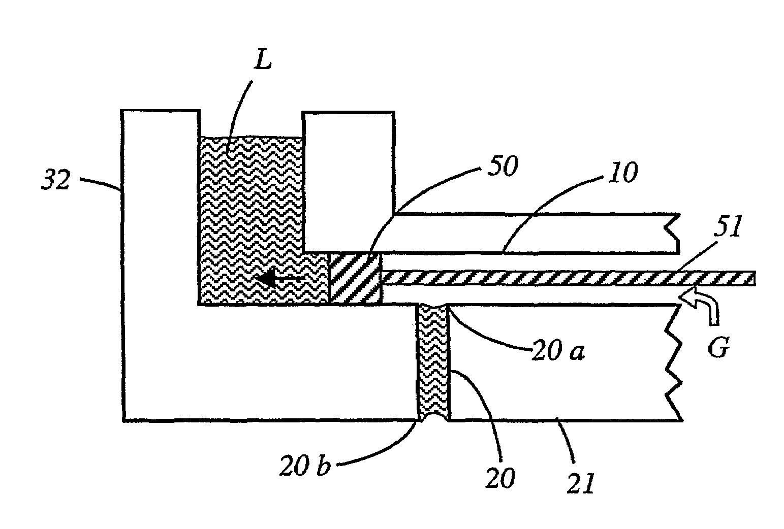
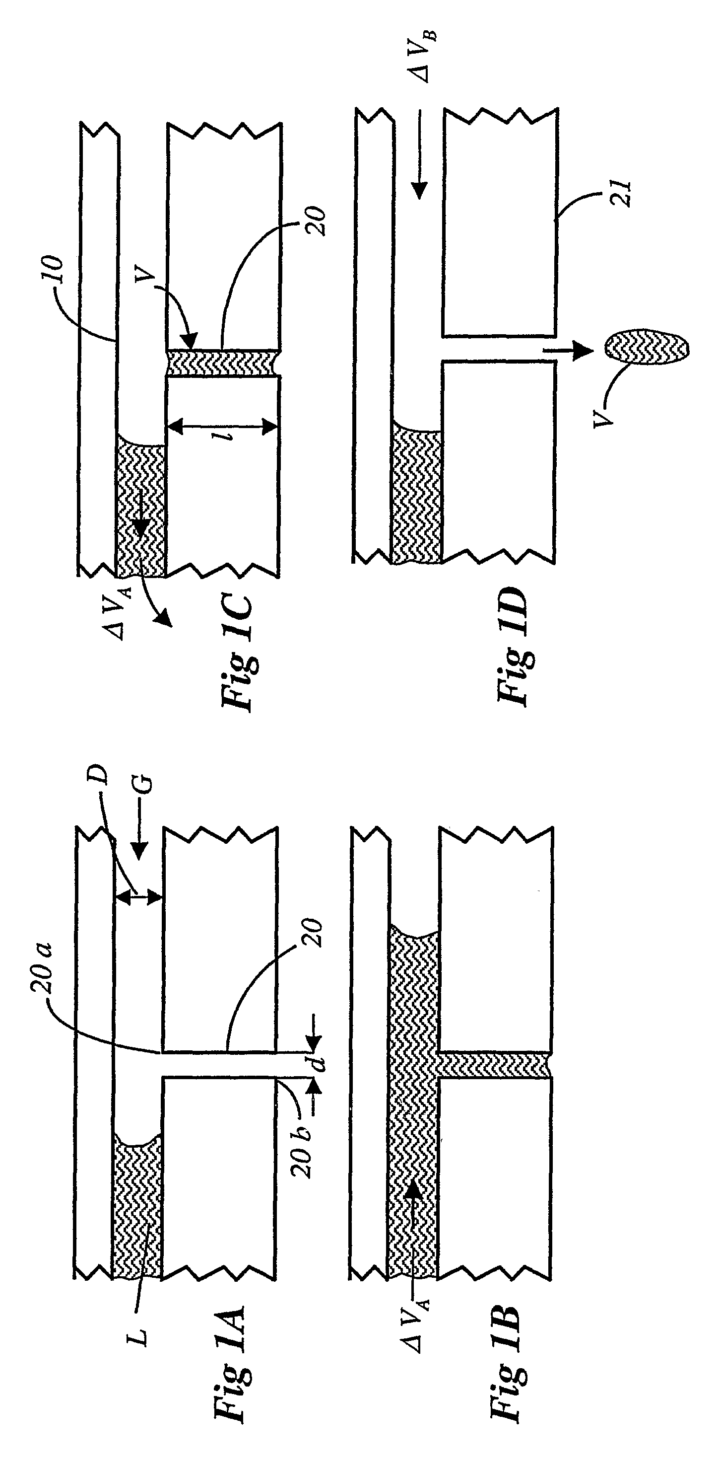
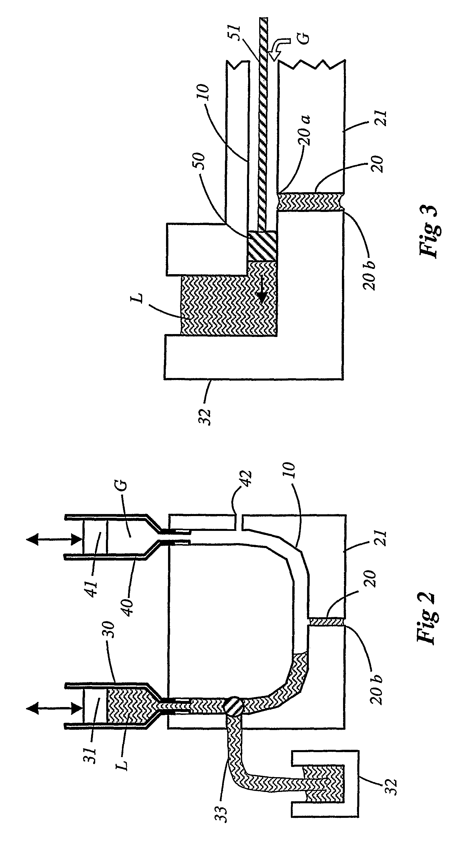
[0043]As shown in FIGS. 1A to 1D and FIG. 2, a device for dispensing small quantities of at least one liquid comprises a supply of liquid L and a supply of gas G arranged to respectively supply the liquid L and gas G (typically air) to opposite ends of a supply duct 10.

[0044]A capillary duct 20 having open first and second ends 20a, 20b, branches from the supply duct 10. The capillary duct 20 has a defined length l and a diameter d of capillary dimensions, much smaller than the diameter D (or cross-dimension) of supply duct 10.

[0045]The ducts 10, 20 are contained in a body of hydrophilic material, or surface-coated with a hydrophilic material, so they can receive aqueous solutions as well as other solvants.

[0046]FIG. 1A shows the device in a rest state, after ejection of a quantity of liquid (FIG. 1D). In this rest state, the liquid L from the supply is withdrawn from the first end 20a of the capillary duct. Gas G from the supply is in communication with the ambient atmosphere via t...


PUM


Abstract

The invention provides a device for dispensing accurately-controlled small quantities of at least one liquid, comprising a liquid supply (L); a gas supply (G), arranged to selectively supply a gas pressure; and a capillary duct (20) adapted to be filled with liquid to be dispensed, and to eject the liquid. The device has a filling configuration wherein liquid from the supply is in contact with an end (20a) of the capillary duct to fill the capillary duct with liquid; and a liquid separation and ejection configuration, in which liquid remaining in the liquid supply is separated from liquid that fills the capillary duct to form a discrete quantity (V) of liquid filling the capillary duct (20) out of contact with the remaining liquid of the liquid supply. The capillary duct, filled with this discrete quantity (V) of liquid then has one end in contact with the gas supply and another end in contact with the atmosphere. The discrete quantity of liquid (V), forming an exact dose of liquid to be dispensed, is ejectable from the second end (20b) of the capillary duct by the application of gas pressure.

Description

FIELD OF THE INVENTION[0001]The invention relates to a device for dispensing small quantities of at least one liquid, useful in a number of contexts including the carrying out of various synthesis as well as diagnostic and drug screening applications, particularly those involving biological materials, where there is a need to precisely dose the dispensed liquid.BACKGROUND OF THE INVENTION[0002]The use of passive capillary valves as a method for controlling fluid flow in a microfluidic system is discussed in “Hydrophobic microfluidics” by McNeely et al, SPIE Conference on Microfluidic Devices and Systems II, Santa Clara, Calif., September 1999, SPIE Vol. 3877-786X / 99.[0003]U.S. Pat. Nos. 5,846,396 and 5,958,344 for example describe a liquid distribution system where liquid is dispensed between a connected feeder channel and a reaction cell via a conduit having a capillary barrier interposed to check the flow. Liquid in the feeder channel remains permanently in contact with the liquid...

Claims


Application Information

Patent Timeline
IPC IPC(8): B01L3/02B65D83/00G01N1/10G01N1/00B01J4/02B67D99/00C40B60/14G01N35/10
CPCB01L3/0241B01L3/0265B01J2219/00315B01J2219/00351B01J2219/00369Y10T436/118339B01L2400/0644B01L2400/065C40B60/14Y10T436/2575B01L2200/0605
Inventor RENAUD, PHILIPPEDONZEL, ALAIN
Owner PARABOL TECH
Why Eureka
Try Eureka