Recording and playback apparatus and optical head including a variable optical coupling efficiency device

a recording and playback apparatus and optical head technology, applied in the field of recording and playback apparatus and optical head including a variable optical coupling efficiency device, can solve the problems of large laser noise, large power consumption of sources with large optical output power, and inability to achieve satisfactory playback characteristics, etc., to achieve excellent recording and playback characteristics, and low laser noise level.

Inactive Publication Date: 2007-06-12
SONY CORP
View PDF12 Cites 1 Cited by
  • Summary
  • Abstract
  • Description
  • Claims
  • Application Information

AI Technical Summary

Benefits of technology

[0013]Accordingly, it is an object of the present invention to provide an optical head, a recording and playback apparatus, and a variable optical coupling efficiency device in which a low laser noise level is achieved during a playback mode even if an output power ratio of write to read power in a light source is small, and excellent recording and playback characteristics are achieved even if a light source easy to manufacture or having a low optical output power rating is used.
[0018]By switching the optical coupling efficiency of the variable optical coupling efficiency device between a write mode and a read mode, the light intensity directed to an optical recording medium is thus substantially varied from the write mode to the read mode. This arrangement eliminates the need for substantially increasing the optical output power ratio of write power to read power on the light source.
[0019]Even if a light source easy to manufacture or having a low optical output power rating is used, an optical beam at an appropriate intensity level is directed to the optical recording medium for recording or playback during a write mode or a read mode, and excellent recording and playback characteristics are achieved.

Problems solved by technology

(1) The semiconductor laser has difficulty in outputting a stable oscillation in a low output power level thereof, and laser noise becomes large in magnitude.
A light source having a large optical output power is not only impracticable but also consumes much power.
If the maximum optical power rating is set to be low, no satisfactory playback characteristics are obtained because of a high noise level during the replay time.

Method used


Image

  • Recording and playback apparatus and optical head including a variable optical coupling efficiency device
  • Recording and playback apparatus and optical head including a variable optical coupling efficiency device
  • Recording and playback apparatus and optical head including a variable optical coupling efficiency device

Examples


first embodiment

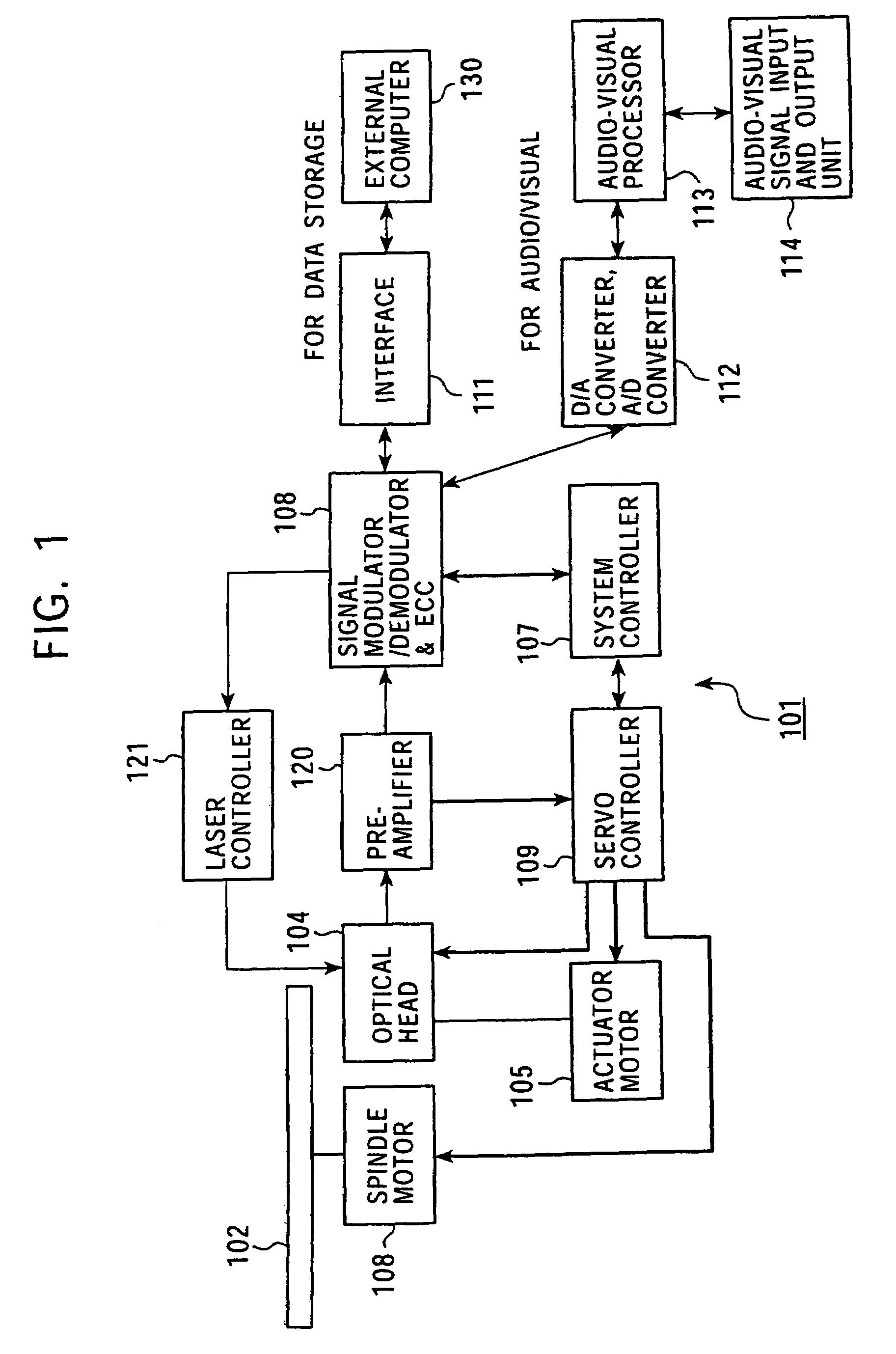
[0035]FIG. 1 is a block diagram of an optical disk recording and playback apparatus 101 incorporating a variable optical coupling efficiency device 3 and an optical head 104 in accordance with the present invention.

[0036]The optical disk recording and playback apparatus 101 shown in FIG. 1 is one example of the recording and playback apparatus that incorporates the variable optical coupling efficiency device 3 and the optical disk 104 to be discussed below.

[0037]As shown, the recording and playback apparatus 101 includes a spindle motor 103 working as a rotary drive for rotating an optical disk 102, an optical head 104, and an actuator motor 105 working as an actuator of the optical head 104.

[0038]The spindle motor 103 is controlled by a system controller 107 and a servo controller 109, and is thus rotated at a predetermined rpm.

[0039]The optical disk 102 may be a recording and playback disk using an optically modulated record signal, such as a “CD-R / RW” disk, “DVD-RAM” disk, “DVD-R...

second embodiment

[0150]An optical head, a recording and playback apparatus, and a variable optical coupling efficiency device for performing a fast recording operation and a fast playback operation in accordance with a second embodiment are discussed below.

[0151]The second embodiment of the present invention is discussed with reference to the construction shown in FIG. 10 again.

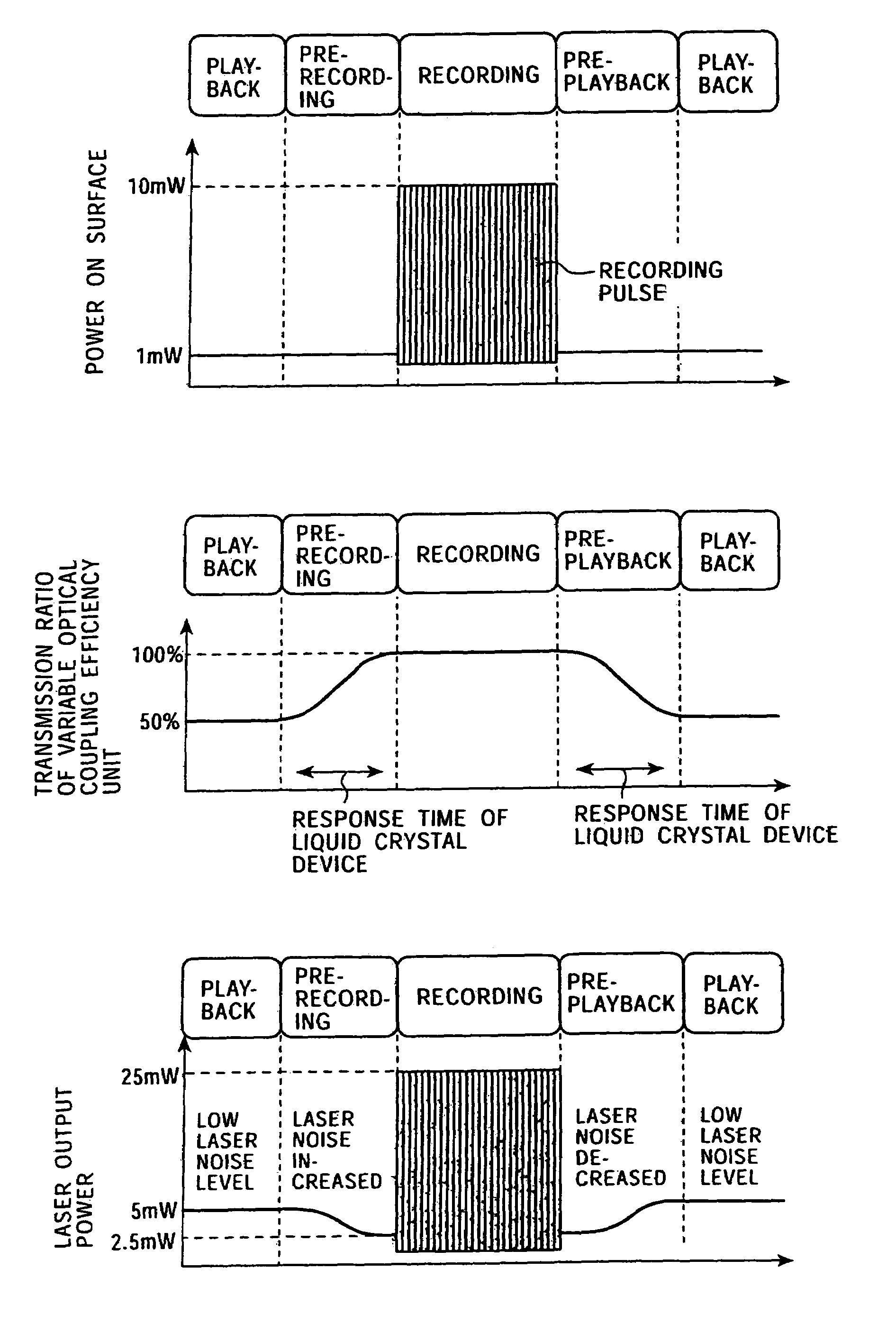
[0152]FIG. 12 is a plot of a change in the transmission ratio of the variable optical coupling efficiency device 3 in response to a response from the wavelength-type liquid-crystal device 214 in accordance with the second embodiment.

[0153]The abscissa represents the voltage applied to the wavelength-type liquid-crystal device 214, while the ordinate represents the transmission ratio of the P-polarized light component. Vread-represents the voltage applied during the read mode, and Vwrite represents the voltage applied during the write mode (the relationship of Vwrite>Vread holds).

[0154]Generally speaking, a response time when ...


PUM

PropertyMeasurementUnit
output poweraaaaaaaaaa
power ratingaaaaaaaaaa
output poweraaaaaaaaaa

Abstract

The light intensity of a light beam emitted from a light source is appropriately controlled when the light beam is transmitted through a variable optical coupling efficiency device in an optical head. During a read mode, the light beam from the light source is incident on an optical disk at an intensity relatively weaker than that of the light source. By switching the optical coupling efficiency of the variable optical coupling efficiency device between a write mode and a read mode, the light intensity directed to an optical recording medium is substantially varied from the write mode to the read mode. This arrangement eliminates the need for substantially increasing the optical output power ratio of the light source of write power to read power.

Description

BACKGROUND OF THE INVENTION[0001]1. Field of the Invention[0002]The present invention relates to a recording and playback apparatus for recording and playing back a variety of pieces of information to and from an optical recording medium, and an optical head for use in an optical apparatus such as the recording and playback apparatus, and a variable optical coupling efficiency device for use in the optical head.[0003]2. Description of the Related Art[0004]Optical recording media such as an optical disk have ruggedness (pits) representing signal information. Some recording media are used as playback purposes only. Some permit recording and playback operations using phase variation along a groove structure or using magneto-optical recording.[0005]The optical head of a recording and playback apparatus such as an optical disk device which employs a write and read optical disk typically uses a semiconductor laser. The semiconductor laser light source typically gives a relatively high max...

Claims


Application Information

Patent Timeline
Patent Type & Authority Patents(United States)
IPC IPC(8): G11B7/135G02F1/13G02B27/28G11B7/125
CPCG11B7/1356G11B7/1369G11B7/1381G11B7/1263G11B7/128G11B7/126G11B7/1365G11B7/1353
Inventor NISHI, NORIAKIMIZUMA, HIROAKIKIMURA, MOTOIYAMAMOTO, KENJINISHINO, MASATOSHI
Owner SONY CORP
Why Eureka
Try Eureka