Compact phase-conjugate mirror and other optic devices

a phase-conjugate mirror and optical device technology, applied in the direction of optical waveguide light guide, optical fibre with polarisation, instruments, etc., can solve the problems of limiting such devices to glass cores and a very limited number, unsuitable guiding structures for low-index media, and several limitations of nonlinear media

Inactive Publication Date: 2007-06-19
HRL LAB
View PDF11 Cites 3 Cited by
  • Summary
  • Abstract
  • Description
  • Claims
  • Application Information

AI Technical Summary

Problems solved by technology

Until now, however, suitable guiding structures did not exist for low-index media such as gases.
Prior to the development of the guided-wave structure (the HC-PCF), PCMs using waveguide geometries were constrained to materials with a refractive index greater than that of the cladding material of the guide (typically glass), thus limiting such devices to glass cores and a very limited number of high-index liquids whose reflective index is greater than that of glass (nglass≈1.5) lightpipes, such as CS2-filled capillaries.
These nonlinear media have several limitations including competing nonlinear interactions, such as self-focusing, photochemical degradation, Raman scattering, and optical breakdown.
Currently, “loop” PCMs are being studied in the high-average power regime, but they have thermal, FOV, and fidelity limitations.
SBS in solids and liquids suffer from optical damage, photochemical degradation, and competing nonlinear optical effects, such as optical breakdown, filamentation, SRS, self-phase modulation and self-focusing.
On the other hand, the photorefractive materials suffer from optical damage (catastrophic, depoling) at high intensities and thermal effects at high optical absorption.
Recently, so-called “loop” PCMs have been employed by HRL and Raytheon with limited success at the required laser powers, but suffer from limited wavefront-reversal fidelity, resulting in a loss of brightness.
The loop devices have design constraints owing to the thermal nonlinearity, which can limit the phase-conjugate fidelity and FOV, especially as one scales to high-average powers.
The optical gain media are promising, but, may also have limitations at high-average powers, since operation is constrained to intensities on the order of the saturation intensity of the medium (where, presumably, the induced gratings have the greatest phase-conjugate Bragg selectivity).
Finally, being an oscillator, the loop geometries are much more complex than passive PCMs (e.g., this invention) and, possess potential pulsation effects, which can cause optical damage at high-powers, as well as potentially damage the materials that are processed by the output power, such as laser welders, etc.
Researchers have, in the past, employed glass cores with in-diffusion of selected gases, such as H2, as a means to realize Raman scattering over long interaction lengths, but, such an approach was not very practical and remained an intellectual curiosity for the past 2 decades.
For long-haul communication links, the technical community also specifies the use of single-mode fibers, since multi-mode fibers can limit the communication bandwidth due to modal dispersion.
Hence, a multimodal fiber would be deleterious in such an application, and therefore, designers of long haul communication systems specifically avoid that class of fiber.
However, in phone discussions (by the first named inventor) with several experts in this technology area, where the topic of multi-mode HC-PCFs was mentioned (not in regard to this disclosure, but, in the general context of modal dispersion), none of the researchers ever considered the topic of multi-mode propagation in these structures, much less polarization effects again since the goal of the technical community involves long-haul fiber communication links.

Method used


Image

  • Compact phase-conjugate mirror and other optic devices
  • Compact phase-conjugate mirror and other optic devices
  • Compact phase-conjugate mirror and other optic devices

Examples


Embodiment Construction

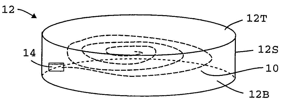
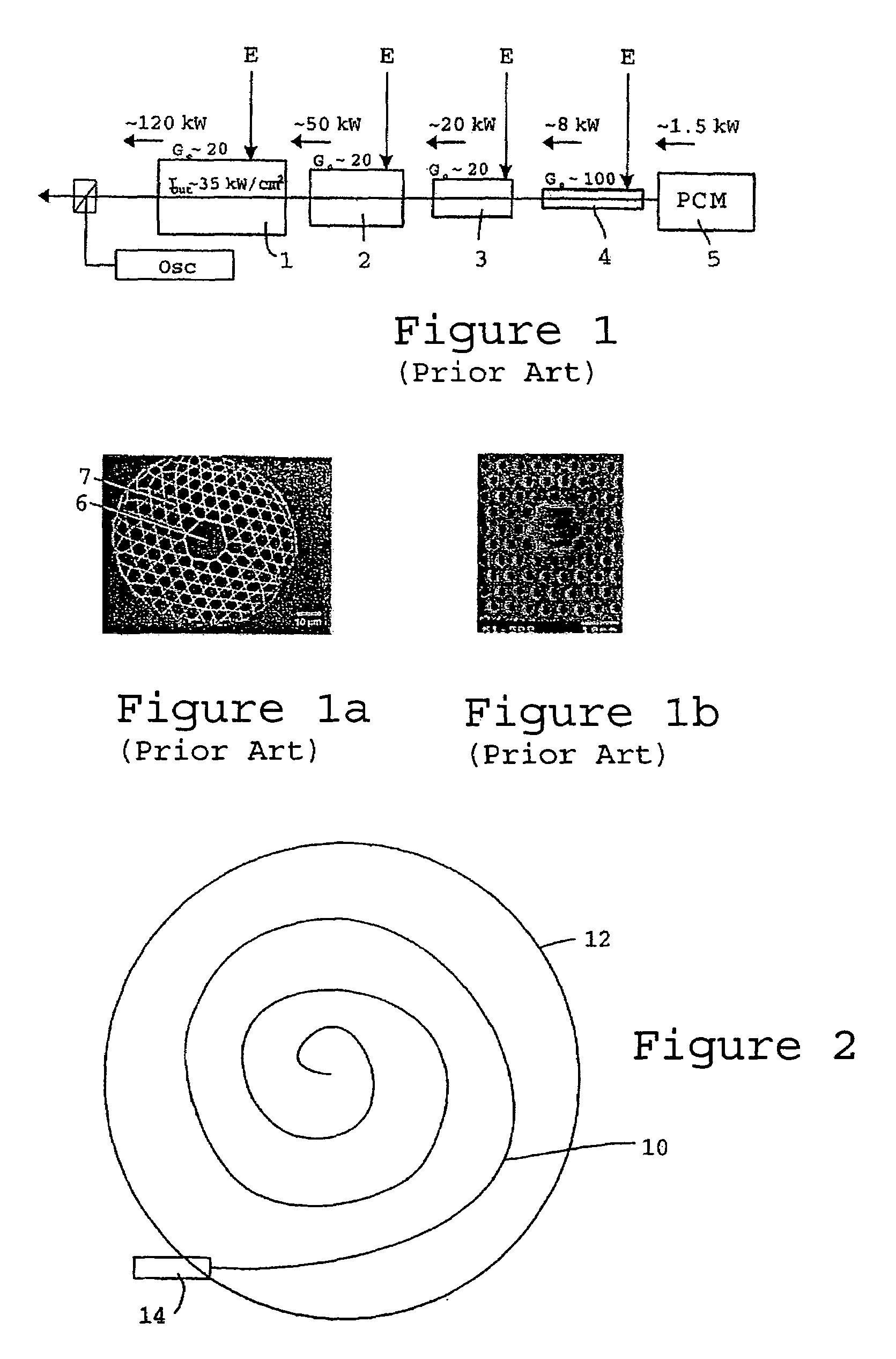
[0022]This disclosure describes a power-scalable Stimulated Brillouin Scattering (SBS) phase conjugate mirror (PCM). This passive PCM utilizes SBS in a novel structure: a multi-spatial mode, polarization-maintaining, gas-filled, hollow-core photonic crystal fiber (HC-PCF). This novel HC-PCF waveguide now enables realization of the simplest and most elegant PCM approach, SBS, in a gas-filled, guided-wave structure. FIGS. 1, 1a and 1b depict a representative PC-MOPA schematic and end views of HC-PCFs by Benabid and the University of Bath. Having the potential for rapid technology insertion into the tens-of-kilowatt laser systems currently under development, the HC-PCF PCM provides the technical community with a viable alternative technology candidates relative to currently pursued technologies, such as “loop” PCMs, etc.

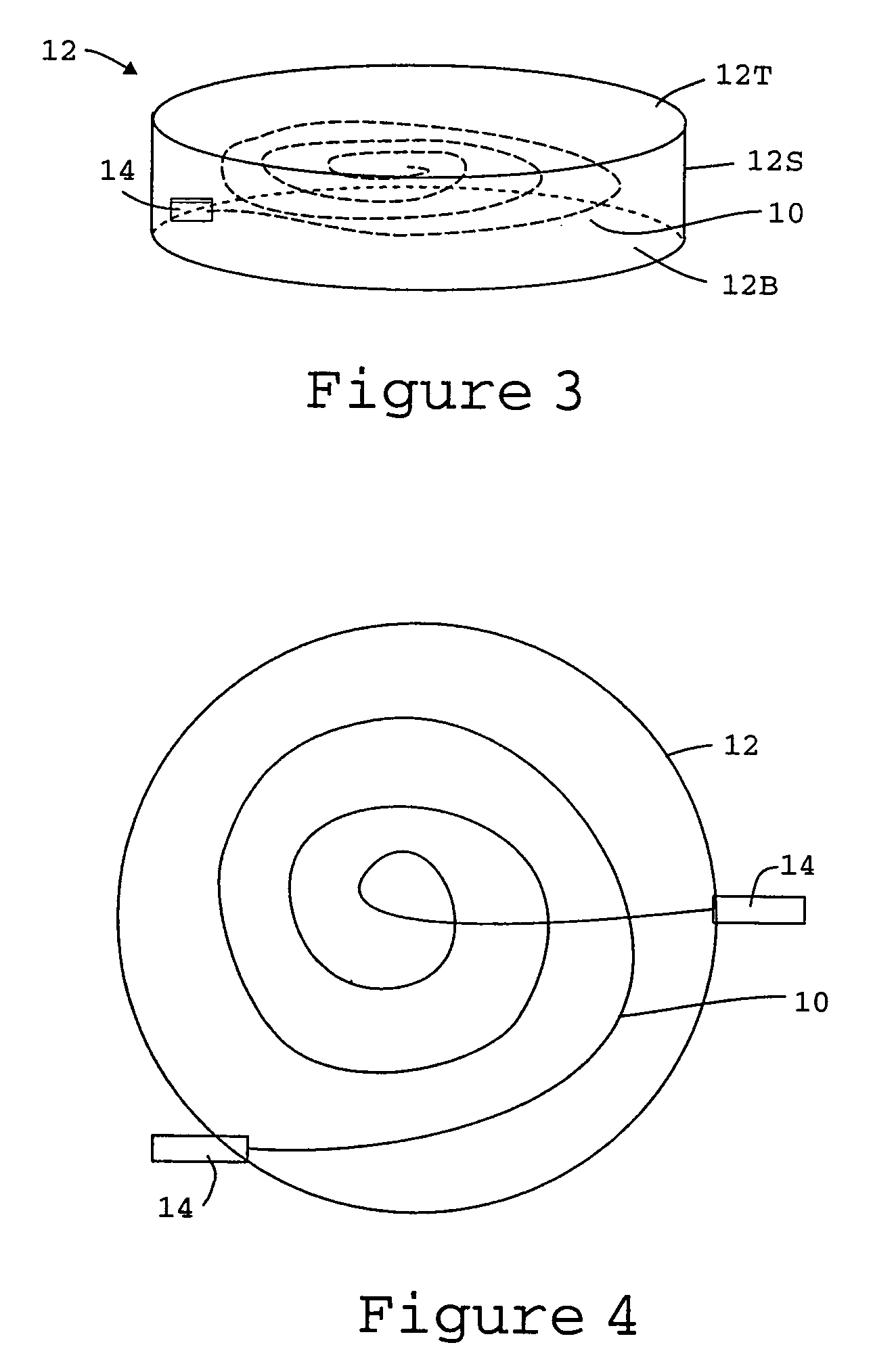
[0023]There are several variants of the basic geometry. For example, the PCM can be realized using a self-pumped configuration, where only a single beam is incident ont...


PUM


Abstract

A phase-conjugate mirror has a length of hollow core photonic crystal multi-spatial mode, polarization-maintaining fiber disposed in a vessel, with a compressible and preferably gaseous medium, such as Xe or CH4, occupying the hollow core of the of hollow core photonic crystal fiber and surrounding the exterior of the hollow core photonic crystal fiber. At least one sealed window is provided in the vessel, the at least one sealed window being optically coupled to at least one end of the length of hollow core photonic crystal fiber.

Description

TECHNICAL FIELD[0001]This invention is directed to the use of a hollow-core photonic crystal fiber (HC-PCF) as a guiding structure for a passive optical devices, including a self-pumped, stimulated scattering, phase-conjugate mirror (PCM).BACKGROUND OF THE DISCLOSURE[0002]Hollow-core photonic crystal fibers are designed to guide optical beams via Bragg reflection at the core / cladding interface along the structure, as opposed to conventional fibers that guide light via total internal reflection along the waveguide. This property enables the fiber to guide light down its “core,” whose refractive index can be less than that of the cladding, even air or vacuum. Owing to the guided-wave nature of these fibers, the hollow core of the fiber can be filled with a variety of low or high refractive-index states of matter, including gases, cryogenic liquids (LN2), or critical-point media (ethane, Freon 113). By using such fibers, long interaction lengths can be realized that can far exceed leng...

Claims


Application Information

Patent Timeline
Patent Type & Authority Patents(United States)
IPC IPC(8): G02B6/02
CPCG02B6/02328G02B6/02338G02B6/02357G02B6/024
Inventor PEPPER, DAVID M.BRUESSELBACH, HANS W.MINDEN, MONICA
Owner HRL LAB
Why Eureka
Try Eureka