
Spark plug with increased durability

a technology of spark plugs and durable parts, which is applied in the direction of spark plugs, machines/engines, mechanical equipment, etc., can solve the problems of increasing the possibility of cracking of porcelain insulators, engine knocking, and mechanical strength decline, so as to reduce the diameter of threads of metal shells, and reduce the size of spark plugs

Inactive Publication Date: 2007-06-26
DENSO CORP
View PDF11 Cites 5 Cited by
  • Summary
  • Abstract
  • Description
  • Claims
  • Application Information

AI Technical Summary

Benefits of technology

[0015]It is another object of the invention to provide an improved structure of a spark plug designed to be compact in size without sacrificing mechanical strength or durability thereof.
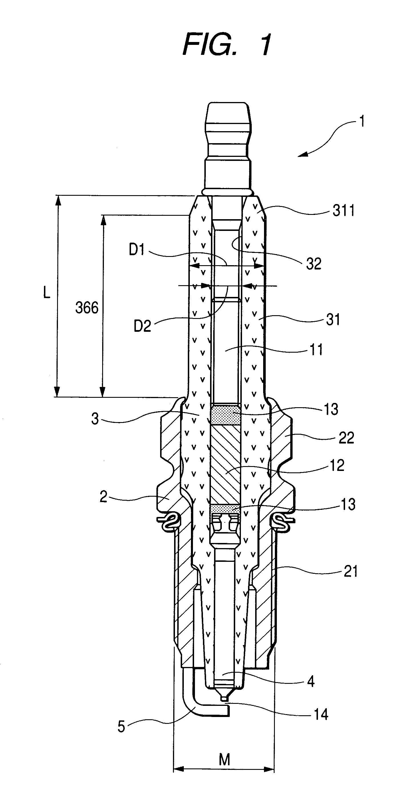
[0017]The section modulus Z which is greater than or equal to 33 mm3 at the smallest-outer diameter portion of the major body ensures a desired degree of strength of the porcelain insulator, especially resistance to external pressure oriented perpendicular to the length of the porcelain insulator to cause bending thereof.
[0018]The outer diameter D1 at the smallest-outer diameter portion of the major body which is within a range of 7.1 mm to 8.8 mm permits the spark plug to be reduced in size without sacrificing the mechanical strength of the porcelain insulator. Specifically, the outer diameter D1 of 8.8 mm or less allows a thread diameter of the metal shell to be decreased, which leads to a reduction in size of the spark plug. The outer diameter D1 of 7.1 mm or more assures the section modulus Z lying within the above range to ensure a required mechanical strength of the porcelain insulator.
[0019]The inner diameter D2 at the smallest-outer diameter portion of the major body which is within a range of 2.8 mm or more ensures mechanical strength of joint of, for example, the center electrode, a terminal electrode, and a resistor retained inside the porcelain insulator to the porcelain insulator. Specifically, the inner diameter D2 of 2.8 mm or more assures an area of, for example, glass seals to be welded to the porcelain insulator, thereby offering a desired strength to fix the center electrode in the porcelain insulator.
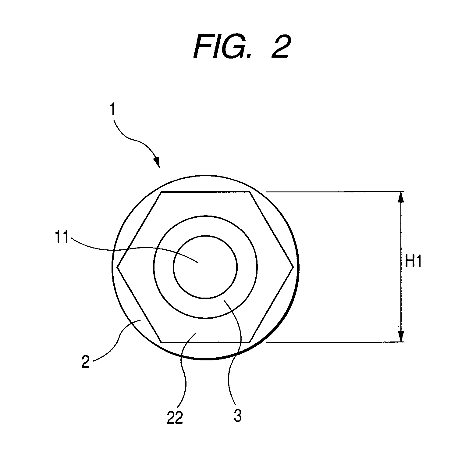
[0020]In the preferred mode of the invention, the metal shell is equipped with a plug installation tool-fitted portion which has a regular hexagonal transverse section extending perpendicular to an axial of the metal shell. A distance H1 between opposite two of sides of the hexagonal transverse section is selected to meet a relation of 11.7 mm≦H1≦14 mm. This permits the spark plug to be reduced in size.
[0023]The insulator head the porcelain insulator has a length L which meets a relation of 22 mm≦L≦28 mm. The ensures the resistance of the insulator head to a mechanical load oriented in a direction perpendicular to the length of the porcelain insulator.

Problems solved by technology

The improvement of the combustion requires improvement of thermal efficiency and compression ratio in the engine which may, however, result in self-ignition of the mixture in combustion chambers of the engine, thus leading to engine knocking.
This, however, results in need for decreasing the diameter of a porcelain insulator of the spark plug, which gives rise to a decrease in mechanical strength thereof.
This increases the possibility of breakage of the porcelain insulator due to engine vibrations.
The above structure, however, has the problem in that engine vibrations may be transmitted to a joint between the ignition coil and the spark plug, so that an undesirable mechanical load or stress is applied to the head of the porcelain insulator of the spark plug.
Specifically, when the engine vibrations applied to the engine head in which the spark plug is installed and the head cover in which the ignition coil is installed differ in direction or phase from each other, it will cause a bending force or stress to act on the porcelain insulator.
Thinning of the porcelain insulator, therefore, increases the possibility of breakage of the porcelain insulator due to the engine vibrations.
When the coil boot is loosen from the head of the porcelain insulator, so that a greater gap exits between them, it may result in the so-called flashover in which the current leaks to the head of the porcelain insulator, which gives rise to a lack of spark in the spark gap, thus decreasing the ignitability of the mixture in the engine.
Particularly, increasing in the spark gap caused by wear of the electrodes of the spark plug will result in a rise in voltage of discharge.
Further, deterioration or hardening of the coil boot caused by long use of the spark plug results in a decrease in electrical insulation ability thereof, which may result in a discharge to the surface of the porcelain insulator (i.e., the flashover), thereby leading to misfiring in the engine.
Conversely, the coil boot is fitted on the head of the porcelain insulator too tightly, a greater effort is required to pull the coil boot out of the spark plug.
A negative pressure or vacuum is, thus, developed in the coil boot, thus resulting in an increase in effort required to pull the coil boot from the spark plug.
If the coil boot is pulled by force, it may result in damage to the coil boot or breakage of or cracks in the porcelain insulator.
Specifically, firm fitting of the coil boot with the head of the porcelain insulator facilitates ensuring of electrical insulation therebetween, but may be a factor of damage to the coil boot or breakage of or cracks in the porcelain insulator.

Method used


Image

  • Spark plug with increased durability
  • Spark plug with increased durability
  • Spark plug with increased durability

Examples


first embodiment

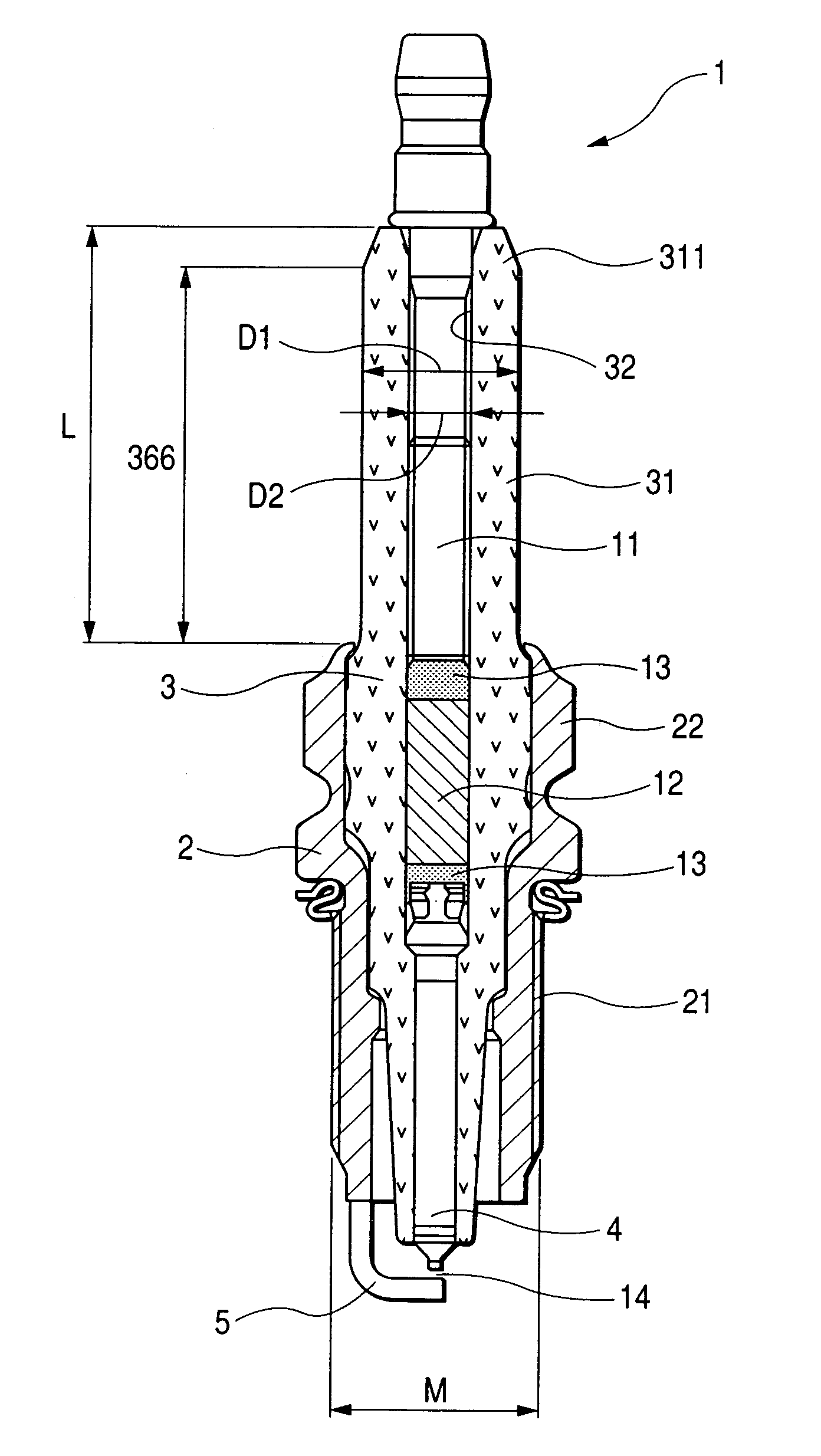
[0037]Referring now to the drawings, particularly to FIG. 1, there is shown a spark plug 1 for automotive internal combustion engines according to the invention.

[0038]The spark plug 1 generally includes a hollow cylindrical metal shell 2, a porcelain insulator 3, a center electrode 4, and a ground electrode 5. The porcelain insulator 3 is retained in the metal shell 2 to have an insulator head 31 extending outside the metal shell 2 toward the base end (i.e., an upper portion as viewed in the drawing) of the spark plug 1. The center electrode 4 is retained in a center hole 32 formed in the porcelain insulator 3. The ground electrode 5 extends from the metal shell 2 and faces the center electrode 4 through a spark gap 14.

[0039]The metal shell 2 has a thread 21 for installation in the internal combustion engine and a hexagonal head 22 on which a wrench is to be fitted to install or remove the spark plug 1 in or from the engine.

[0040]The insulator head 31 has a length L extending outsid...

third embodiment

[0068]FIGS. 5 and 6 show the spark plug 1 according to the invention which has the insulator head 31 with ribs or corrugations. The corrugations extend in a circumferential direction of the insulator head 31 and are each defined by a bottom or trough 312 and a peak or top 313.

[0069]The insulator head 31, as clearly shown in FIG. 6, has the outer diameter D1, as identical with the one in the first embodiment, at the troughs 312.

[0070]The major body 366 of the insulator head 31, like the first embodiment, has an outer peripheral area of 400 mm2 to 600 mm2 that is an area of the outer surface of the insulator head 31 to be in contact with the coil boot 631 of the ignition device 6 of FIG. 3 and illustrated in FIG. 6 by a solid heavy line. Specifically, the outer peripheral area is an outer area of the major body 366 within a depth range of 0 mm to 0.1 mm from the top 313 of each of the corrugations. In other words, it is an outer side area of a portion of the porcelain insulator 3 exte...


PUM


Abstract

A spark plug is provided which is designed to be compact without sacrificing a mechanical strength of a porcelain insulator. The spark plug includes a metal shell having a base end and a top end. The porcelain insulator is made of a hollow cylinder which includes a body and an insulator head. The body is retained within the metal shell. The insulator head extends from the base end of the metal shell in a lengthwise direction of the porcelain insulator and has a length made up of a major body leading to the body of the porcelain insulator and an end portion lying far away from the body. The major body has an outer diameter D1, an inner diameter D2, and a section modulus Z at a smallest-outer diameter portion thereof which meet relations of 7.1 mm≦D1≦8.8 mm, D2≧2.8 mm, and Z≧33 mm3.

Description

CROSS REFERENCE TO RELATED DOCUMENT[0001]The present application claims benefits of Japanese Patent Application No. 2004-252885 filed on Aug. 31, 2004 and Japanese Patent Application No. 2005-170684 filed on Jun. 10, 2005 the disclosures of which are incorporated herein by reference.BACKGROUND OF THE INVENTION[0002]1. Technical Field of the Invention[0003]The present invention relates generally to a spark plug with increased durability for internal combustion engines which may be used in automotive vehicles, co-generation systems, or gas feed pumps.[0004]2. Background Art[0005]Internal combustion engines used in, for example, automotive vehicles employ spark plugs to ignite an air-fuel mixture. Such spark plugs are being increasingly required to improve combustion in the engine for reducing the fuel consumption or emissions thereof. The improvement of the combustion requires improvement of thermal efficiency and compression ratio in the engine which may, however, result in self-igni...

Claims


Application Information

Patent Timeline
Patent Type & Authority Patents(United States)
IPC IPC(8): F02P1/00H01T13/20
CPCF02P3/02H01T13/08H01T13/20
Inventor ABE, NOBUOKAWASHIMA, YASUSHIGOTO, TSUNETOSHI
Owner DENSO CORP
Learn More