Liquid interface configurations for automated patch clamp recording

a technology of automated patch clamping and liquid interface, which is applied in the direction of liquid/fluent solid measurement, instruments, electrochemical variables, etc., can solve the problems of difficult sealing formation, difficult to position the micropipette tip, and debris at the interface, so as to facilitate the attachment of the cell, accurate and repeated positioning

Inactive Publication Date: 2007-07-10
BRISTOL MYERS SQUIBB CO
View PDF6 Cites 6 Cited by
  • Summary
  • Abstract
  • Description
  • Claims
  • Application Information

AI Technical Summary

Benefits of technology

[0011]With the subject invention, a method is provided for automating the patch clamp technique for testing electrophysiological properties of cells, including cellular resistance, capacitance, transmembrane potential, and conductance. The technique may be used to evaluate cellular features which affect the aforementioned electrophysiological characteristics, such as ion channels and electrogenic transporters. The subject invention enables cells to be accurately and repeatedly positioned relative to the tip of a micropipette so as to allow the tip to contact one of the cells. The method further facilitates the attachment of the cell to the pipette and generation of an acceptable seal therewith and is usable with both whole cell and on cell configurations. (As used herein, and generally understood in the art, the term “whole cell” refers to a testing configuration where an aperture formed in a pipette is in communication with a hole that extends through the lipid bi-layer (i.e., membrane) of a cell such that electrophysiological data obtained during testing result from the cell's entire plasma membrane, and its constituent ion channels and / or electrogenic transporters, thus, the “whole” cell. As used herein, and generally understood in the art, the term “on cell” refers to a testing configuration where an aperture formed in a pipette does not communicate with the interior of a cell (i.e., the pipette contacts partially or wholly intact membrane).)

Problems solved by technology

In the prior art, the act of positioning the micropipette tip is tedious, requiring initial cell location (e.g., on a dish; in a cell bath); and, positioning the micropipette properly relative to the located cell.
Several deficiencies, however, are found with this technique.
First, debris collects at the interface and interferes with, and even spoils, the ability to have seal formation.
Second, the meniscus at the interface creates difficulties in developing seal formation.

Method used


Image

  • Liquid interface configurations for automated patch clamp recording
  • Liquid interface configurations for automated patch clamp recording
  • Liquid interface configurations for automated patch clamp recording

Examples


Embodiment Construction

[0025]Referring to the Figures, a method is provided for automating the patch clamp technique for testing electrophysiological properties of cells, including cellular resistance, capacitance, transmembrane potential, and conductance. In addition, this method may be used to evaluate cellular features, such as ion channels and electrogenic transporters.

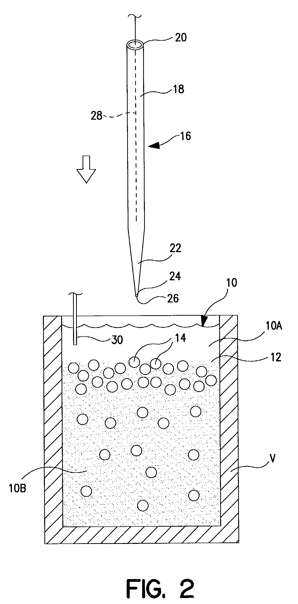
[0026]With reference to FIG. 2, a liquid suspension 10 of at least first and second layers 10A and 10B is shown with an interface 12 being defined therebetween. The liquid suspension 10 may be accommodated in any vessel V known to those skilled in the art, such as a well of a multiwell plate. The densities of the first and second layers 10A and 10B are desirably distinct such that the layers are generally stratified with the interface 12 being defined therebetween. The densities may be generally fixed throughout each layer or lie within a range of densities for each layer (e.g., gradiently disposed), although it is preferred that the de...


PUM

PropertyMeasurementUnit
densityaaaaaaaaaa
densityaaaaaaaaaa
densityaaaaaaaaaa

Abstract

A method of automatically conducting patch clamp testing is provided wherein a liquid interface is utilized. The liquid interface is defined in a liquid suspension between layers of distinct densities such that cells introduced into the liquid suspension float towards the interface. Thus, the cells are locatable relative to the interface.

Description

CROSS-REFERENCE TO RELATED APPLICATION[0001]This application claims priority to U.S. Provisional Patent Application No. 60 / 338,715, filed Nov. 30, 2001.FIELD OF THE INVENTION[0002]The present invention relates generally to techniques for repeatedly positioning an instrument relative to one or more cells for testing and, more particularly, to an automated technique for positioning a pipette or an array of pipettes for measuring cellular electrical properties including ion channel currents, membrane potential, transporter flux and cell capacitance.DESCRIPTION OF THE PRIOR ART[0003]Ion channel measurement plays an important role in determining the effect of compounds and the like at the cellular level. Ion channels are transmembrane proteins that form pores in a cell membrane, which, in turn, allow ions to pass from one side of the cell membrane to another. The activity of these channels influences cell membrane potential and are responsible for mediating changes in overall cell excita...

Claims


Application Information

Patent Timeline
Patent Type & Authority Patents(United States)
IPC IPC(8): C12Q1/00C12M1/34C12Q1/02G01N27/22G01N27/416G01N33/15G01N33/483G01N33/487G01N33/50
CPCC12M1/3407G01N33/48728
Inventor BULLEN, ANDREWWEAVER, CHARLES DAVID
Owner BRISTOL MYERS SQUIBB CO
Why Eureka
Try Eureka