Clock recovery circuit

a clock recovery and clock technology, applied in pulse generators, pulse manipulation, pulse techniques, etc., can solve the problems of not being able to achieve high-speed data communication, clock recovery circuits are not suitable for superfast data transmission, and cannot be precisely received on the receiver side. , to achieve the effect of facilitating clock frequency and higher-rate data transmission

Inactive Publication Date: 2007-07-10
SOCIONEXT INC
View PDF9 Cites 19 Cited by
  • Summary
  • Abstract
  • Description
  • Claims
  • Application Information

AI Technical Summary

Benefits of technology

[0009]By replacing a proper clock edge with a data edge every time a transition of the input data signal is detected, the phases of the multiphase clocks from the first oscillator are optimized. Therefore, the phase relationship between the input data signal and the multiphase clocks can be locked instantaneously with the start of data transmission, and this enables support of burst mode transmission.
[0010]By setting the phase interval of the plurality of clocks from the first oscillator to be equal to the data rate of the input data signal, the oscillating frequency of the first oscillator is 1 / N of the data rate of the input data signal, where N is the number of stages of the delay cells included in the first oscillator. By this setting, the clock frequency is eased compared with the conventional clock recovery circuit, and thus higher-rate data transmission can be supported.

Problems solved by technology

In data communications over some distance, such as data communications between mutually connected equipment units, if a data path and a clock path are provided separately, the phase relationship between the data and the clock set on the transmitter side may not be precisely received on the receiver side in some cases, due to a difference in path length and a difference in distortion level.
As a result, high-speed data communications may not be attained.
Therefore, this clock recovery circuit is not suitable for superfast data transmission.

Method used


Image

  • Clock recovery circuit
  • Clock recovery circuit
  • Clock recovery circuit

Examples


embodiment 1

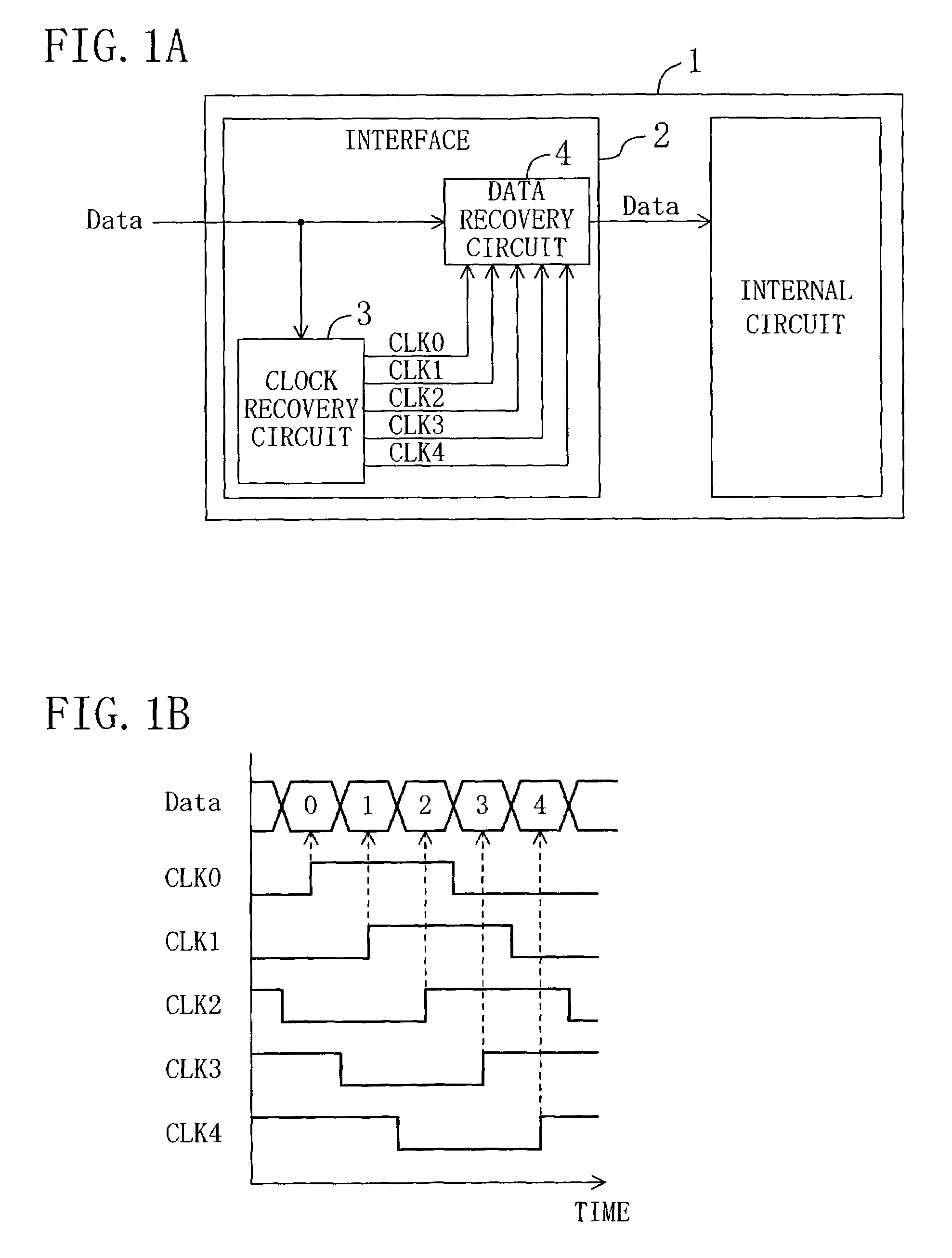
[0056]FIG. 1A shows a schematic configuration of electronic communication equipment in Embodiment 1 of the present invention. In this electronic communication equipment, denoted by 1, an input data signal Data from outside is supplied to an internal circuit via an interface 2. The interface 2 includes a clock recovery circuit 3 and a data recovery circuit 4. The clock recovery circuit 3 extracts multiphase clocks CLK0 to CLK4 synchronizing the input data signal Data from the input data signal Data. The phase interval (phase difference) of the multiphase clocks CLK0 to CLK4 is equal to the data width defined by the data rate of the input data signal Data. The data recovery circuit 4 recovers the input data signal Data with the multiphase clocks CLK0 to CLK4 sent from the clock recovery circuit 3. Specifically, as shown in FIG. 1B, the data recovery circuit 4 recovers one data unit of the input data signal Data at each edge of the phases of the multiphase clocks CLK0 to CLK4. The inpu...

embodiment 2

[0094]In the clock recovery circuit of Embodiment 1, the mask window is desirably generated so that a transition point of the output of the preceding delay cell (that is, the clock to be replaced) is included in the mask window and located at the center thereof.

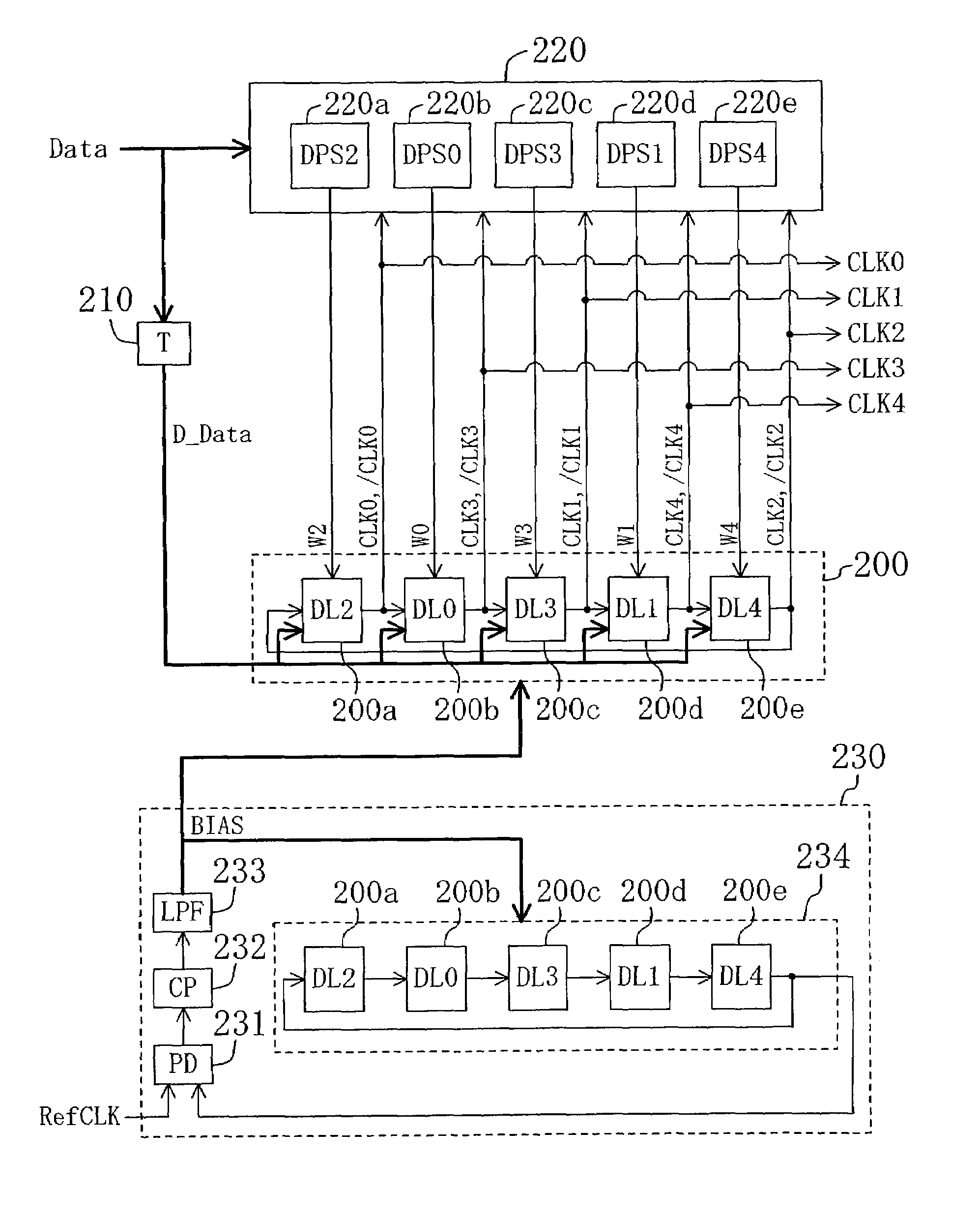
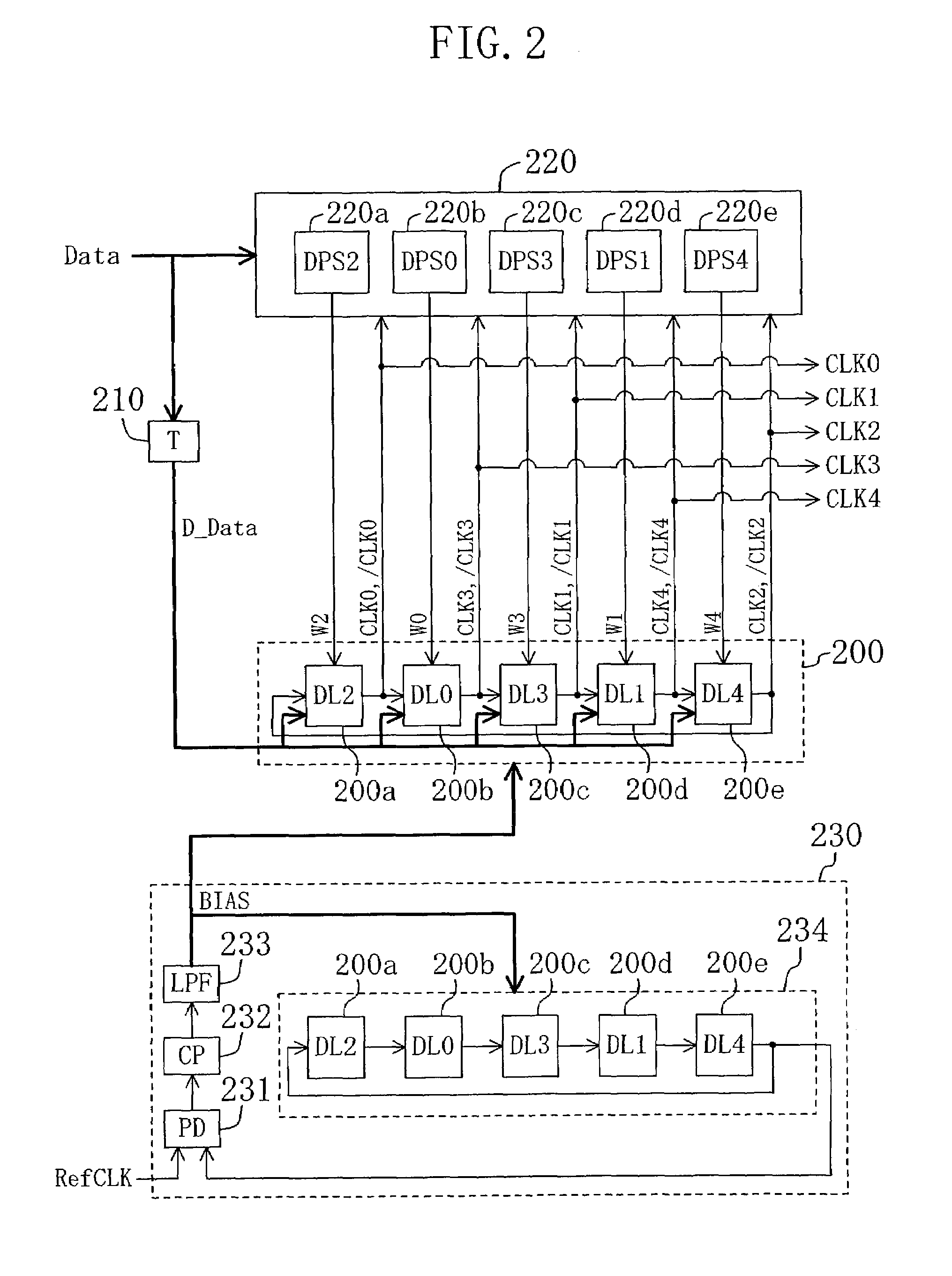
[0095]In Embodiment 1, however, no consideration is given to delays generated in the delay path selectors 220a to 220e during generation of the mask signals W0 to W4. For example, in the delay path selector 220e of FIG. 4A, a gate delay (delay amount tg1) is generated in the NAND circuits 303a and 303b during generation of the signals D0 and D1 from the clocks CLK0 and / CLK21 and the clocks CLK1 and / CLK2. Likewise, a gate delay (delay amount tg2) is generated in the NOR circuit 302 during generation of the mask signal W4 from the signals D1 and EN0. These delays are also generated in the delay path selectors 220a to 220d.

[0096]The influence of the delays described above is greater as the data rate of the input data signal D...

embodiment 3

[0115]FIG. 9 shows a configuration of a clock recovery circuit of Embodiment 3. The clock recovery circuit of this embodiment includes a delay circuit 210, an edge detector 220, a voltage-controlled oscillator (VCO) 500, a PLL 530, phase comparators 540a to 540e and a control circuit 550.

[0116]The VCO 500, oscillating at a frequency corresponding to a bias voltage BIAS from the PLL 530 and a bias voltage BIAS3 from the control circuit 550, includes 5-stage delay cells 500a to 500e connected in a ring. Each of the delay cells 500a to 500e reverse-delays a signal output from the preceding delay cell by a delay amount according to the bias voltage BIAS from the PLL 530 and the bias voltage BLAS3 from the control circuit 550. The outputs (CLK0, CLK3, CLK1, CLK4, CLK2) of the delay cells 500a to 500e are output outside the clock recovery circuit as multiphase clocks CLK0 to CLK4.

[0117]The PLL 530 includes a phase comparator 231, a charge pump 232, a low-pass filter 233 and a voltage-cont...


PUM


Abstract

The clock recovery circuit includes a first oscillator and an edge detector. The first oscillator generates a plurality of clocks having different phases and a predetermined frequency. The edge detector detects two clocks, among the plurality of clocks, between edges of which an input data signal has made a transition. The first oscillator includes a plurality of delay cells connected in a ring, and outputs of the plurality of delay cells are output as the plurality of clocks. Each of the plurality of delay cells selectively delays a first-delay added input data signal or the signal output from the preceding delay cell, and outputs the selected delayed signal. The edge detector controls one delay cell among the plurality of delay cells corresponding to the result of the detection, to delay and output the first-delay added input data signal.

Description

BACKGROUND OF THE INVENTION[0001]The present invention relates to a clock recovery circuit, and more particularly, to a clock recovery circuit for extracting multiphase clocks synchronizing with data from the data.[0002]For transmission / reception of data, a clock is necessary together with the data. The clock is a signal serving as a reference of timing for retrieval of the data. In data communications over some distance, such as data communications between mutually connected equipment units, if a data path and a clock path are provided separately, the phase relationship between the data and the clock set on the transmitter side may not be precisely received on the receiver side in some cases, due to a difference in path length and a difference in distortion level. As a result, high-speed data communications may not be attained. To solve this problem, a clock recovery technology is adopted in which a clock is extracted from transitions of data on the receiver side and recovered.[000...

Claims


Application Information

Patent Timeline
Patent Type & Authority Patents(United States)
IPC IPC(8): H04L7/00H04L7/02H03K5/00H03K5/135H03L7/07H03L7/081H03L7/087H03L7/099H04L7/033
CPCH03K5/135H03L7/07H03L7/0805H04L7/0037H03L7/087H03L7/0995H04L7/0337H03L7/081H03K2005/00208H04L7/0041
Inventor IWATA, TORU
Owner SOCIONEXT INC
Why Eureka
Try Eureka