Diesel engine with differential cylinder group operation

a technology of differential cylinders and diesel engines, which is applied in the direction of machines/engines, output power, electric control, etc., can solve the problems of low exhaust temperature, low heat generation efficiency, and device temperature sensitiveness, so as to increase heat, increase heat, and increase heat

Inactive Publication Date: 2007-07-24
FORD GLOBAL TECH LLC
View PDF6 Cites 33 Cited by
  • Summary
  • Abstract
  • Description
  • Claims
  • Application Information

AI Technical Summary

Benefits of technology

[0005]In this way, by using intake retard or exhaust advance on cylinders with less torque, it is possible to have a torque differential and also increase heat from both cylinder groups. In other words, both cylinder groups are able to generate at least some heat, and one group is able to generate increased heat due to operating at increased torque (to balance reduced torque of other group), while the other group is able to generate increased heat due to adjusted valve timing. Further, heat generation can be further enhanced in the other group, for example, by operating with adjusting fuel injection timing, amount, or number of injections. An advantage of such operation is that the cylinders providing less torque can do so without necessarily requiring increased throttling via a throttle in the intake (thus avoiding potentially increased pumping work).BRIEF

Problems solved by technology

However, these devices may be sensitive to temperature, and engine operation may be adjusted to maintain these devices at specific operating temperature.
The issue with temperature generation in the engine can be particularly difficult in diesel combustion systems, where increased combustion efficiency results in relatively low exhaust temperature.
While such operation may increase exhaust heat, the inventors herein have recognizes that it may be relatively fuel inefficient due to the engine braking operation.
Further, the differential torque between the cylinders may produce unacceptable vibration as some cylinders are producing negative torque while some are producing positive torque.
However, the inventors herein have recognized that such operation may still provide inefficient heat since the cylinders operating at the lower power level produce relatively low amounts of heat.
Further, the cylinders may produce a differential level of combustion torque.

Method used


Image

  • Diesel engine with differential cylinder group operation
  • Diesel engine with differential cylinder group operation
  • Diesel engine with differential cylinder group operation

Examples


Embodiment Construction

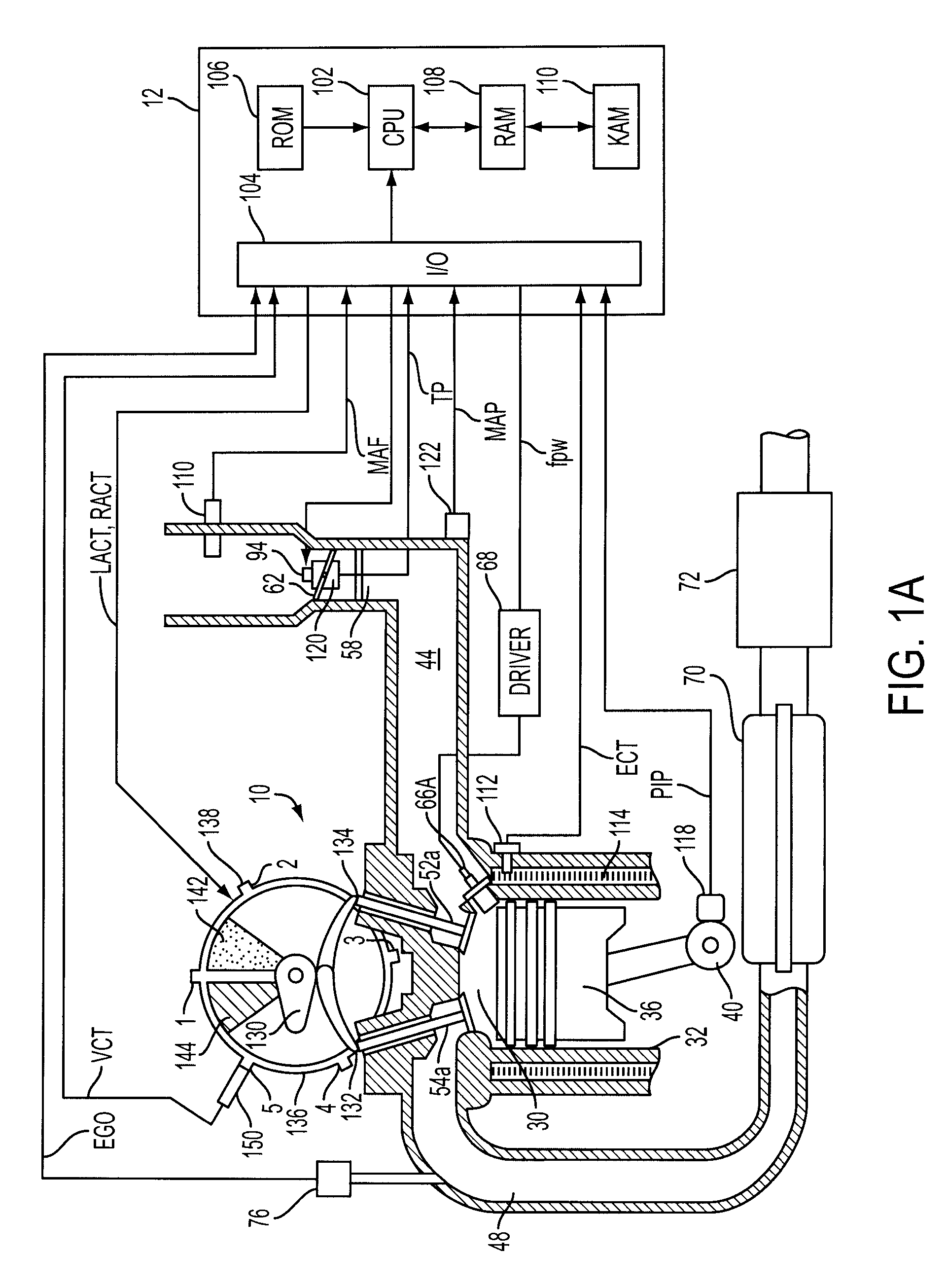
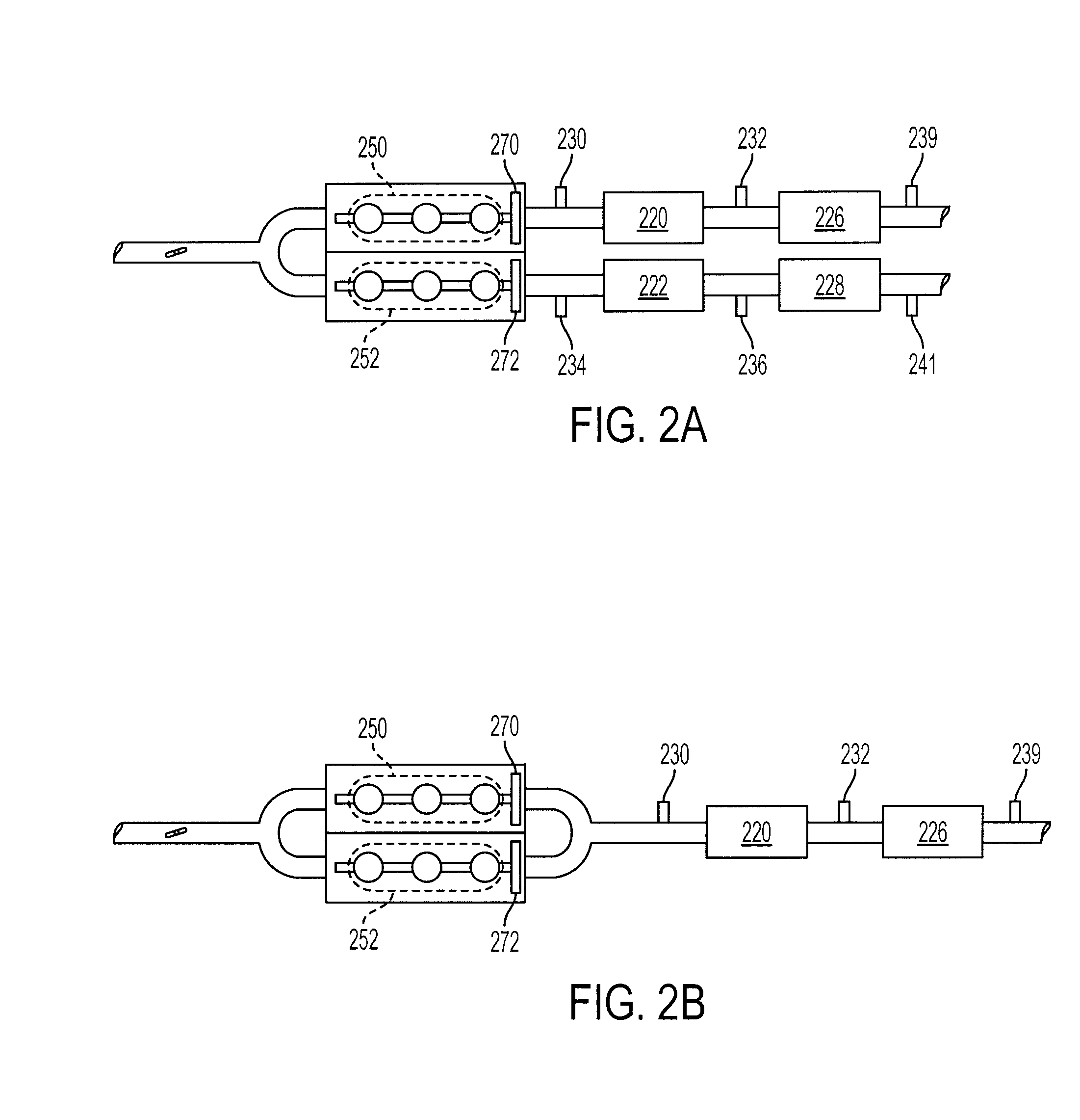
[0010]FIG. 1 shows one cylinder of a multi-cylinder engine, as well as an intake and exhaust path connected to that cylinder. As described later herein with particular reference to FIG. 2, there are various configurations of the cylinders and exhaust system.

[0011]Continuing with FIG. 1, direct injection compression ignition internal combustion engine 10, comprising a plurality of combustion chambers, is controlled by electronic engine controller 12. The engine may be a diesel engine wherein compression ignition is initiated via direct injection of fuel, for example. Combustion chamber 30 of engine 10 is shown including combustion chamber walls 32 with piston 36 positioned therein and connected to crankshaft 40. A starter motor (not shown) is coupled to crankshaft 40 via a flywheel (not shown). Combustion chamber, or cylinder, 30 is shown communicating with intake manifold 44 and exhaust manifold 48 via respective intake valves 52a and 52b (not shown), and exhaust valves 54a and 54b ...


PUM


Abstract

A method for controlling operation of a diesel engine having a plurality of cylinders, the engine including a first group of cylinders and a second group of cylinders, the method comprising of operating the first group of cylinders with a first intake and exhaust valve timing, the first group of cylinders inducting air and performing diesel compression ignition combustion of injected fuel; and operating the second group of cylinders with a second intake and exhaust valve timing, the second group of cylinders inducting air and performing diesel compression ignition combustion of injected fuel, wherein said second intake valve timing is retarded compared to said first intake valve timing or said second exhaust valve timing is advanced compared to said first exhaust valve timing.

Description

BACKGROUND AND SUMMARY[0001]Engines may use various devices to reduce release of regulated emission. For example, engines may use emission control devices that perform various catalytic reactions to reduce release of regulated emissions. However, these devices may be sensitive to temperature, and engine operation may be adjusted to maintain these devices at specific operating temperature. The issue with temperature generation in the engine can be particularly difficult in diesel combustion systems, where increased combustion efficiency results in relatively low exhaust temperature.[0002]One approach to provide increase heating is described in U.S. '790. According to this approach, exhaust heating can be performed where some cylinders are in high load condition, and some cylinders are in an engine braking condition. While such operation may increase exhaust heat, the inventors herein have recognizes that it may be relatively fuel inefficient due to the engine braking operation. Furth...

Claims


Application Information

Patent Timeline
Patent Type & Authority Patents(United States)
IPC IPC(8): F02B3/08
CPCF01N13/011F02D13/0215F01N13/009F02B73/00F01L1/3442F01L2001/0535F01L2800/00F01L2800/08F01N13/107F02D41/029F02D41/1443Y02T10/18F02D41/0082F02D41/402F02D13/0265Y02T10/12
Inventor HOARE, GRAHAMSURNILLA, GOPICHANDRA
Owner FORD GLOBAL TECH LLC
Why Eureka
Try Eureka