
Manipulator for automatic screwdriver

a manipulator and screwdriver technology, which is applied in the direction of power-driven tools, wrenches, metal-working devices, etc., can solve the problems of inconvenient change of screw spacing, and achieve the effect of convenient and convenient installation, high flexibility and portability, and convenient us

Active Publication Date: 2007-07-31
CALZONE RONALD JOHN
View PDF2 Cites 2 Cited by
  • Summary
  • Abstract
  • Description
  • Claims
  • Application Information

AI Technical Summary

Benefits of technology

"The invention is a safer, more economical way to install self-tapping or self-drilling screws while maintaining flexibility and portability. It allows for the placement of screws with greater flexibility and ease of use compared to large fixtures. The invention can be fixed in place or portable on a truck or trailer bed, and it reduces the need for multiple screwdrivers. It also provides a more efficient means of manufacturing processes and reduces costs in both initial procurement and maintenance. Overall, the invention offers a better solution for manufacturing processes that require flexibility and portability."

Problems solved by technology

Said large fixtures generally fix the placement of the screwdrivers so that a desired change in the spacing of the screws is inconvenient.

Method used


Image

  • Manipulator for automatic screwdriver
  • Manipulator for automatic screwdriver
  • Manipulator for automatic screwdriver

Examples


Embodiment Construction

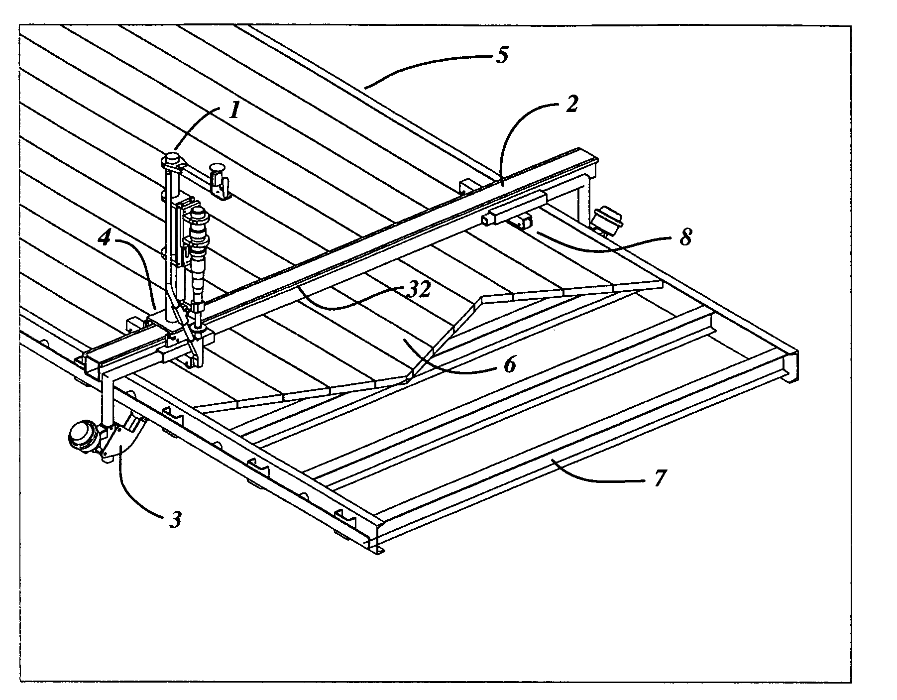
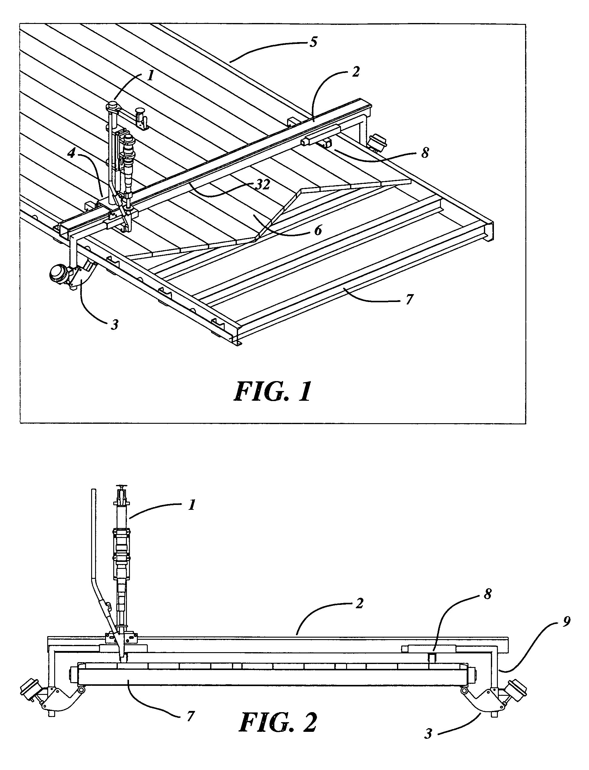
[0024]Referring to FIGS. 1 and 2, numeral 1 generally refers to the automatic screwdriver manipulator of this invention. It is shown employed on the flat deck of a truck or trailer 5 with the decking material and cross members of said deck indicated by numerals 6 and 7, respectively. The invention applies screws to fasten the deck material 6 to the cross members 7.

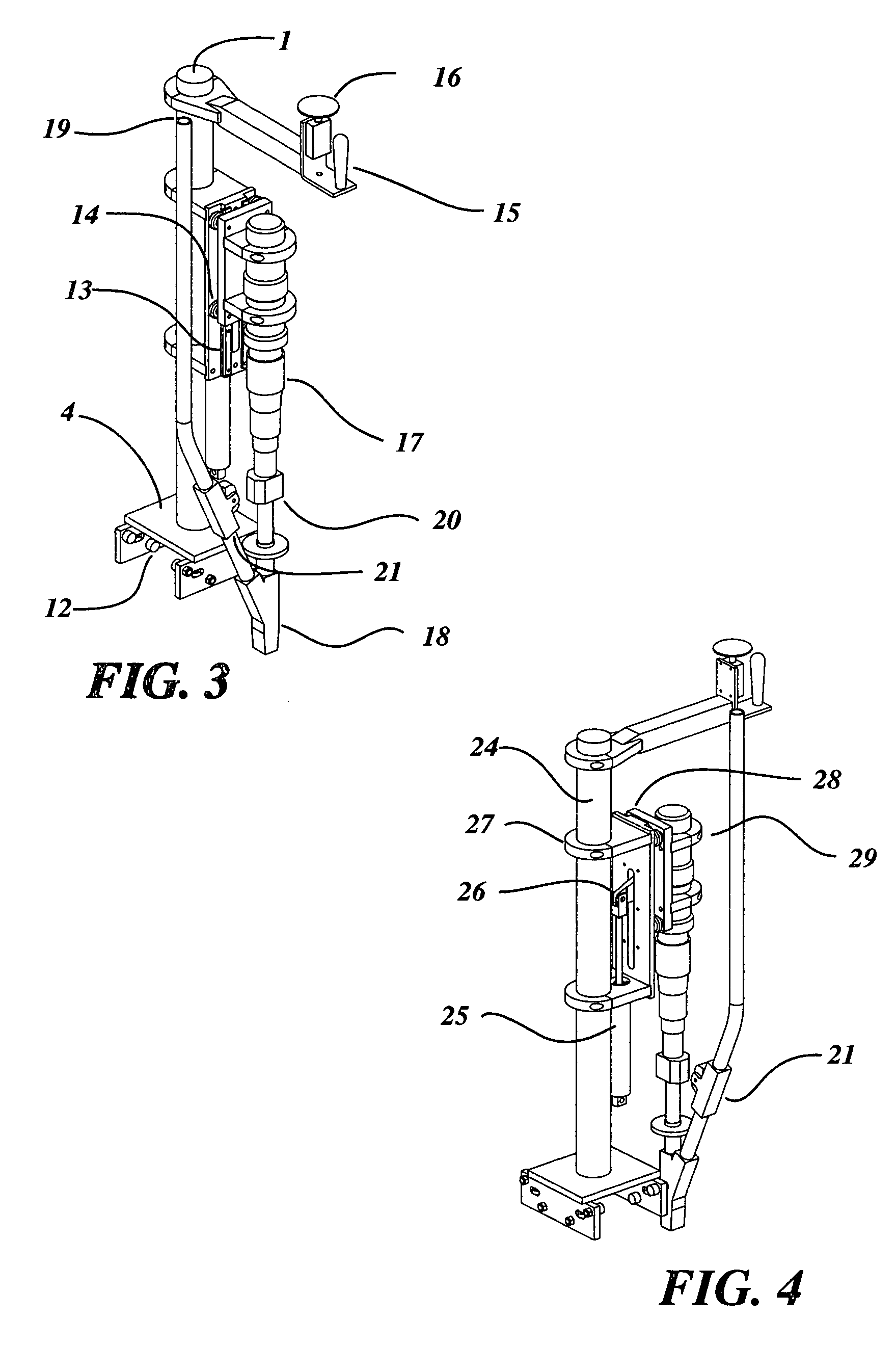
[0025]The screwdriver manipulator of this invention is comprised of a cross beam 2, supported by wheeled trucks 8 which facilitate the easy movement of the entire assembly longitudinally along the length of the deck. The cross beam is clamped securely in place during operation by clamps 3 on either end of the cross beam. The carriage 4 freely moves laterally across the width of the deck on rails 32 which are integral with the cross beam 2. This carriage resolves axial and torsional forces resulting from the screw driving operation while facilitating lateral movement from screw position to screw position across the width of...


PUM


Abstract

The instant invention relates to the manufacture and / or repair of trailer and truck decks or similar. In particular, the invention relates to the installation of self tapping screws into pre-drilled holes or the installation of self drilling, self tapping screws where no hole yet exists. The machine has a cross beam with rails for a wheeled carriage which supports a linear actuator for an automatic screwdriver or, in another variation, a screw driving machine with an integral linear actuator. This wheeled carriage facilitates the movement of the screwdriver in a straight line in the X direction, laterally, across the deck, while wheeled trucks on the cross beam allow it, along with the carriage, to be moved in the Y direction, longitudinally, down the length of the deck. The actuator moves the screwdriver axially (Z direction) with each installation of a screw. Said movement is facilitated by a linear actuating device, such as a pneumatic cylinder. Because the cross beam is positioned parallel to a row of holes which have been drilled by a drilling device on the same or a similar cross beam, the operator, or other facility for X or lateral positioning, is relieved of the need to position the screw driver in the Y or longitudinal direction. The instant invention positions the screw driver in a plumb orientation, advances the automatic screwdriver to the work surface and resolves the torque and thrust which results from the application of the screws. It also supports the screw driver the correct height above the deck and facilitates proper countersinking, where desired.

Description

[0001]The application herein is pursuant to prior application No. 60 / 601,769, filed Aug. 16, 2004, the priority of which is hereby claimed.CROSS-REFERENCE TO RELATED APPLICATIONS[0002](Not Applicable)STATEMENT REGARDING FEDERALLY SPONSORED RESEARCH OR DEVELOPMENT[0003](Not Applicable)REFERENCE TO SEQUENCE LISTING[0004](Not Applicable)BACKGROUND OF THE INVENTION[0005]Previously is was necessary to utilize either large and cost prohibitive fixtures or laborious and fatiguing manual techniques for installation of deck screws in truck and trailer decks and the like. Hand held impact wrenches and electric drills required the operator to work on his knees or in a stooped posture. Stand up “T” handle screwdrivers place the operator in a more ergonomic posture, but require a relatively high skill level for the operator to place the screwdriver bit, which is on the end of the long tool, into the head of the screw, which is at his feet. In the case of screwdrivers with an automatic screw feed...

Claims


Application Information

Patent Timeline
Patent Type & Authority Patents(United States)
IPC IPC(8): B25B23/06B25B21/00
CPCB23P19/06
Inventor CALZONE, RONALD JOHN
Owner CALZONE RONALD JOHN
Learn More